Braking and Stopping
Article 20
In earlier articles we saw that, if we try and decelerate a high inertia load too quickly, the motor will act as a generator, and energy will return to the drive, resulting in an overvoltage trip. There are several ways to prevent this happening. Sometimes using a slower deceleration rate will be enough to limit the returned energy.
On most variable frequency drives it’s possible to set a ‘coast to stop’ function. This turns off the drive and allows the load to coast to a stop in its own time (see article 6).
If is necessary to stop the load quickly, or if a controlled stop is needed, then a braking resistor can be fitted (on most drives) which dissipates the regenerative energy (see article 14)
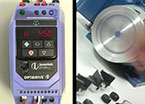
But in many cases we want to stop and hold the load. DC injection will not only produce a braking torque, but will also a holding torque. That is, the rotor will be held in a fixed position as long as DC injection is applied. This can be useful in production, where an item is held for a short time, for labelling for example. However, the holding torque is limited, and DC injection for a long time may cause overheating in the motor. If we need a really good brake, we need an electromechanical brake. These can be separate units, or (more often) are built into the motor. The motor can usually be ordered with the brake assembly included as an option.
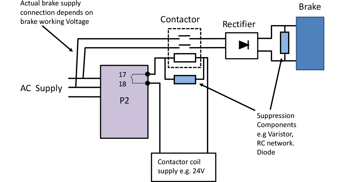
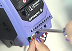
The brake is operated by an electromagnet; that is, when current flows through the controlling coil, the magnetic field lifts the brake and allows the shaft to turn freely. So if the power fails the brake engages. The coil is usually fed from DC, so a separate connection and rectifier is usually required. Remember when switching the coil the switch contacts must be properly rated, and voltages generated by switching must be suppressed with Varistors, Resistor/Capacitor or diode networks.
So far, so good. With a motor connected directly to the mains, we power the brake and the motor together and off we go. But things are a little more complicated if we use a variable frequency drive.
Firstly, we must supply separate power to the brake, as the drive will be feeding the motor with a variable voltage, variable frequency supply which is not suitable for brakes. We now have to decide when to release the brake. In an application such as a horizontal conveyer, the brake can be released as we enable the drive, and the conveyer will start up smoothly. However, if we do the same with a crane or a hoist, the brake will be released before the torque has built up in the motor, and the load may drop suddenly.
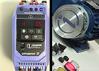
The simple solution to this is to ensure that the variable frequency drive is up and running at a good output before releasing the brake. You can do this on a simple drive by controlling the brake from the drive’s built in relay and releasing the relay when the drive’s frequency has reached a suitable value. Invertek’s E3 drive will open (or close) the relay at any current or frequency threshold you choose to set (see P-18 settings 6). With a bit of care you can set the relay so there is enough torque present to ensure the drive takes up the load smoothly as the brake is released. Of course, the relay will switch again as the frequency falls, so you’ll need to check the stopping timing as well.
For more exacting applications the Invertek P2 drive has a better solution. The second of the two built in relays is used to control the brake. Now, when the drive is operated in ‘hoist mode’, and a start command is given, the drive increases its output frequency to a selected value, and holds at that value. The torque builds up in the motor, and is measured by the drive. Once it reaches the desired value, the brake is released by releasing the relay. The drive holds at the same output frequency for a short time to allow the brake time to release (if required), and then increases the output frequency to the normal running level. When the stop command is given, the drive reduces the frequency to a preset value, applies the brake and holds at the frequency while the brake engages, then reduces the frequency to zero and switches off the drive. This hoist sequence ensures the brake is released and applied under controlled conditions, while the torque is monitored. Torque Proving, as it is known, is essential for safe operation of cranes and hoists. Application note AN-ODP-2-034 gives more details, and the overall sequence is shown in Figure 1
.jpg)
Elevator applications are a little harder as there is usually a counterweight in the system, so that when the brake is released the car may tend to rise or fall, depending on the load. Similar techniques are used to control the brake; often an encoder will make it easier to work out what’s happening and improve the response of the drive.
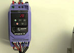
Remember that the brake cannot be controlled directly from the small relay built into the drive. Use the relay contacts to control a suitable contactor, and make sure the all contacts have suppression components fitted to prevent arcing. Figure 2 shows a typical wiring arrangement for a brake control. Note that a separate supply is needed to energise the contactor; the drive will not supply sufficient 24V power to control the contactor.