Variable Frequency Drives in Practice
Article 3
In the last article we discussed the theory behind the design of a variable frequency drive; now we’ll look at the practical design and construction of a VFD.
The previous article described how a variable frequency drive consists of power semiconductors (usually rectifier diodes and IGBTs), a DC link with a capacitor and some sophisticated control and interface electronics. We’ll need to package this to suit the installation in an industrial cabinet, or simply on a wall next to a fan or pump.
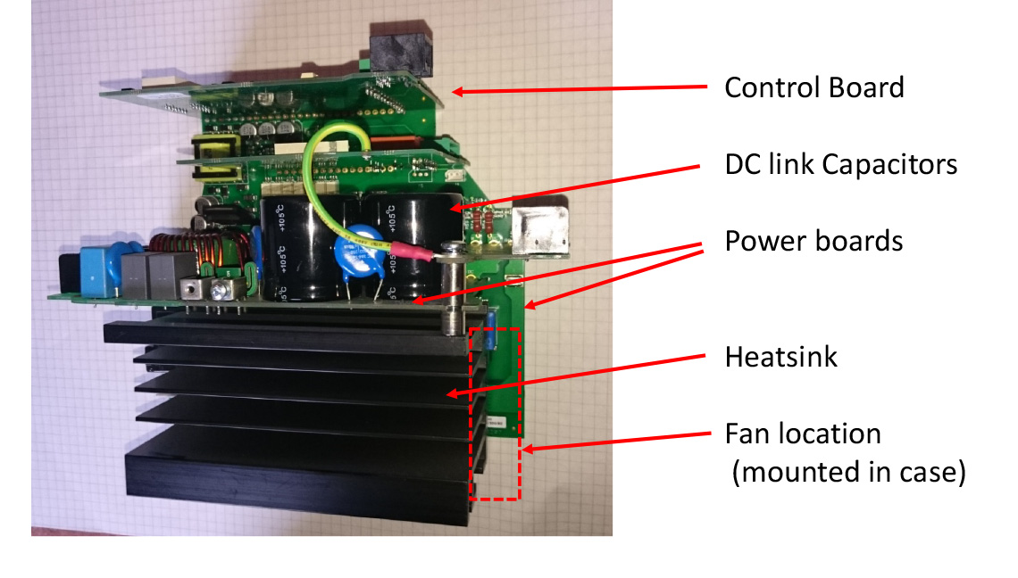
The power electronics usually come in a single package with a mounting plate – a power module. As these components dissipate heat, they need to be fixed to a heatsink, usually an aluminium extrusion or casting. The heatsink will have a fan or fans to cool it, except for the smallest units. It’s an advantage if the fan only switches on if the heatsink is getting hot, as the fans can wear out over time, as well as blow dirt, dust and fluids into the VFD.
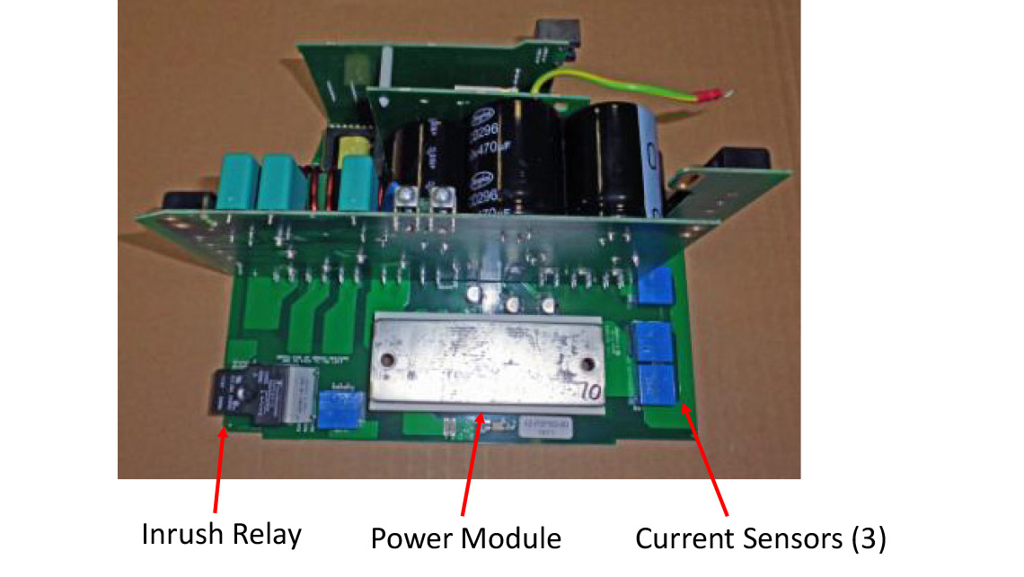
There will usually be at least one ’power’ printed circuit board close to the power module to carry the circuits associated with the IGBTs. There will be gate drive circuits, a power supply, current measurement circuits and an inrush circuit. All these will interface to the control circuit – more of this later.
Each IGBT requires a gate drive circuit. These turn the IGBT on and off as needed, and are connected directly to the IGBT and therefore to the power part of the variable frequency drive. The gate drives will also need a power supply, so actually four separate supplies are needed, one for each ‘upper’ IGBT and a common one for the three ‘lower’ IGBTs. As the power supply needs to supply the control electronics, the fans, and everything else, it becomes rather complicated. Usually a small IGBT supplies a high frequency transformer from the DC link, the secondaries of which feed the various supply regulators.
Current measurement is important and difficult in a variable frequency drive. Important because we need to monitor the output currents (to give good motor control and protection) and possible short circuit currents to protect the IGBTs. Difficult because the measurement points are in the output (or DC link) of the VFD and need power and isolation to get the signal back to the control circuitry. In practice this means using several Hall effect sensors to measure the current in the output, and one or two fast sensors or resistive shunts in the DC link.
The DC link capacitor will be mounted on a power board as well, and when the variable frequency drive is first switched on it will be uncharged, so a circuit consisting of a relay and resistor is used to limit the inrush current. The capacitor charges through the resistor and the relay shorts the resistor after a couple of seconds for normal operation.
So that’s the power pcbs. On the largest variable frequency drives they will be connected to the IGBTs and capacitors by hard wiring or bus bars; on smaller VFDs everything will be mounted onto one or more power boards.
The control electronics will usually be split between the power pcbs and the control board. A special integrated circuit on a power board will generate the on and off signals for the gate circuits. This will be controlled from the main processor on a separate control board; communication between the two will use a fast serial link. This makes isolation of the control board easier. It is important to remember that isolation here (using optocouplers) is necessary as the power pcb is connected to the DC link, and hence the mains.
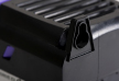
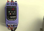
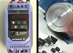
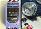
Figure 1 shows the outside of a small variable frequency drive; the major components can be seen when the plastic covers are removed, as in Figures 2 and 3.
-Variable-Frequency-Drive.jpg)
So much for the inside of the variable frequency drive. What about the interfaces to the user?
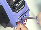
Well, the power terminals will be mounted on a power pcb, easily accessible, and will be robust enough for the size of cable.
The terminals on the control board will be smaller, as these generally handle lower voltages and currents. Variable frequency drives usually have a variety of control and monitor connections, such as programmable digital inputs, analog inputs, analog outputs and relay connections. The digital inputs can start and stop the VFD, reverse the motor direction, select fixed frequencies etc. The analog inputs can be used to control the motor speed, or may be connected to sensor when the variable frequency drive is operating in closed loop control mode. Analog outputs and relays may be used to indicate a fault, as well as ‘running’, ‘speed reached’ etc. All these connections can be programmed to suit the user. Most variable frequency drives will also have some form of serial interface such as Modbus or Canbus to allow control and monitoring in a larger system. This may be via a separate connector such as an RJ45.
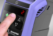
At the front of the variable frequency drive there should be some buttons and a simple display to set up or control it, although on some VFDs this is an option. The display may consist of simple seven segment LEDs, or a full text display which carries more information in many languages. All these control connections, buttons and displays, are mounted on the main control board.
All this needs to be packaged. For smaller variable frequency drives, a simple plastic box, cunningly fitting around the terminals, pcbs etc. is the solution. For larger VFDs, a substantial steel casing and covers (with terminal access) is needed.
If the variable frequency drive is mounted in a cubicle or machine, an IP20 case may be suitable. However, if the unit is mounted on the wall in a plant or process area, a higher level of protection is better, such as IP55 or greater. Many - but by no means all - VFD suppliers will offer these options. This is an important consideration as many variable frequency drives fail as a result of contamination of the electronics by dirt or liquids.
In the next article we’ll look at how to select a variable frequency drive, and how to get started using and installing it.