Commissioning and Troubleshooting Variable Frequency Drives
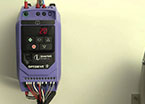
Commissioning a Variable Frequency Drive
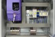
In the last article we described how to connect up the drive and how to install it. Now we’ll see if we can get it going.
Full ArticleSetting up a Variable Frequency Drive
Now we need to look at the basic parameters that match the drive to the motor and the application. In Invertek variable frequency drive, the first thirteen parameters can be adjusted to suit most applications; more parameters are available for specialist applications – we’ll look at those later.
Full ArticleUsing the Inputs on a Variable Frequency Drive
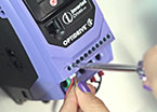
There are many ways to control a variable frequency drive, but often the analogue and digital inputs are used. These can be programmed in many different ways. On Invertek’s E3 drive parameters P-15 and P-12 can be used to select favourite settings for the two digital and two analogue or digital inputs. On P2 and Eco drives P1-13 and P1-12 do this, and there is more flexibility with these drives. Note that the functions of controls built into some IP66 drives will change if these parameters are adjusted.
Full ArticleClosed Loop Control with Variable Frequency Drives
A closed loop control system is one where the actual value that is desired (temperature, pressure, speed etc.) is measured, and the resulting signal connected back to the controlling device, in this case a variable frequency drive.
Full ArticleWarnings, Trips, Faults and Failures
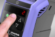
Variable speed drives are pretty reliable these days. Most failures are caused by contamination (dust, dirt, water etc.) or misuse, such as connecting the supply to the output. To help protect itself and the motor, the drive will give a warning (on Invertek drives the decimal points flash to show this) when there is a problem. If the problem persists, the drive will trip – that is, switch off its output to the motor and indicate a fault in the display.
Full ArticleHow to Break a Variable frequency Drive
Most variable frequency drives are installed correctly and give reliable operation. However, if they are incorrectly wired up, or poorly protected, they can fail.
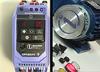
Full ArticleElectromagnetic Compatibility
Electronic systems and controls are everywhere, and as they have spread the problem of interference between equipment has grown. Unwanted signals were being transmitted from wires and printed circuit tracks, and were being received in other equipment. Signals were also finding their way along control cables and power connections. In some cases these signals would interfere with the operation of a machine, causing minor – or occasionally major problems and faults. Engineers began to understand the problem of Electromagnetic Compatibility (EMC) and modified their designs to reduce transmission of interference and improve the product’s immunity to incoming electrical noise. Regulations were introduced to ensure all equipment met certain basic standards. Designers of power supplies and variable frequency drives added input filters and made many other changes in order to meet regulations such as EMC Directive 2004/108/EC.
Full ArticleProblems with motors and cables
Induction motors are designed to work from the mains. However, a variable frequency drive produces a series of high voltage pulses that build up an approximate sinusoidal current in the motor. Most motors run from a drive without problems, and the high switching frequencies used by modern drives create a pretty good sine wave current. The voltage waveform however, can cause problems. The waveform contains many frequencies higher than the switching frequency, and these can cause interference and leakage currents if there is any stray capacitance. Cables between the motor and the variable frequency drive will always have some capacitance to ground, and screened cables are generally worse than loose or unscreened cables – which aren’t recommended as they can cause interference. The longer the cable the greater the capacitance, so drives are usually specified with a maximum cable length. If the capacitance is too great, then the drive may trip on over current or overheating as the leakage current becomes excessive.
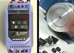
Full ArticleCooling Matters
All electronic equipment will fail if it gets too hot – usually if the semiconductors get above 125oC , so some thought needs to be given to cooling them, especially with variable frequency drives, which generate significant heat themselves.
Full ArticleOptitools Studio
Serial communications connections are available on most variable frequency drives and as well as simplifying wiring and control allow drives to be commissioned and monitored using a PC program such as Invertek’s Optitools Studio. This is free to download from the website and runs with most Windows operating systems
Full Article