Closed Loop Control with Variable Frequency Drives
Article 9
We’ve mentioned a few times how closed loop control is used to maintain constant temperature, pressure etc., and how most drives have this feature built into the drive, so few external components are needed. Let’s look at this in detail.
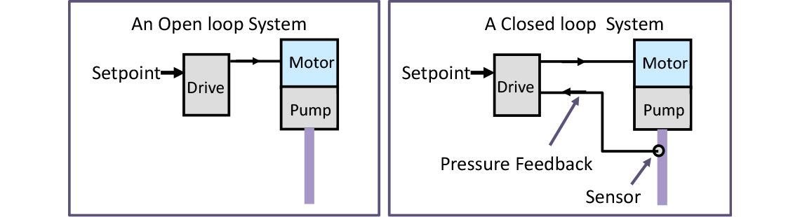
Firstly, let’s talk about the difference between open and closed loop control. If we are using a pump to maintain pressure, we can set the speed of the pump to what we think will do the job, and hope for the best, and maybe turn it down a little at night. This is an open loop control.
A better solution is to fit a pressure transducer and connect that to a variable frequency drive controlling the motor which is driving the pump. The drive will now compare this actual (i.e. measured) pressure value with the desired value (the setpoint) and will adjust the speed of the pump continually to keep the pressure at this level – assuming you’ve set it up correctly. Because the connection from the pressure sensor completes the loop (drive – motor – pump output – transducer – drive) the system is known as a closed loop control system, and is shown in Figure 1.
Closed loop control is used everywhere, from aircraft stabilising systems to tension control in winding systems, as well as more obvious applications maintaining pressure, flow rate, speed or temperature.
A key issue with closed loop control is stability. If you’ve tried to control a narrow boat you’ll know about this; you pull the tiller, nothing happens; you pull it some more and the boat begins to turn. You back off the tiller, but the boat continues to turn. You pull hard the other way and eventually it straightens up. You straighten the tiller, but the boat continues to turn. You oscillate your way down the canal until you get the hang of the delay in the system. In a closed loop system the stability can be established by careful processing of the error. The error is the difference between the Setpoint (the desired value) and the actual (feedback) value. The error is applied to the controlling system – the tiller (and you) on the boat, or the variable frequency drive in industry. So on the narrow boat the difference in where the boat is pointing (actual value) and straight down the canal (Setpoint) is the error, and this tells you to move the tiller.
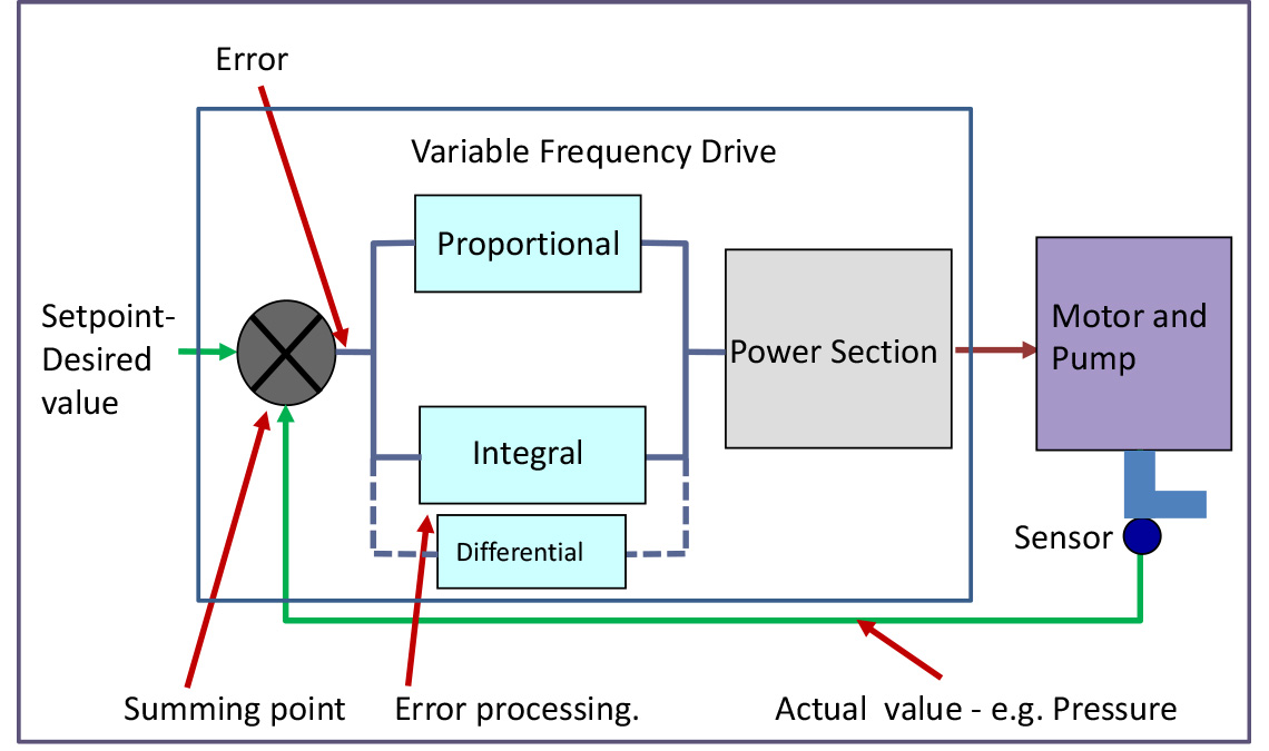
In a typical variable frequency drive application the Setpoint (say pressure) may be set by an analogue input or fixed value, and the actual value by a pressure transducer connected to another analogue input. The error then continually adjusts the motor speed. Now to get good control as well as stability you need to process the error signal. On the narrow boat, you soon learn not to turn the tiller too hard, and to slow down your response to error. The variable frequency drive does this by controlling the Proportional Gain and Integral (filtered value) of the error signal. The Differential value of the error is seldom used, but the three terms, Proportional, Integral and Differential result in the alternative name for a closed loop control system; a PID system.
Let’s look at this more closely. If we multiply the error by a constant this represents a gain. If this constant is a high value, then the slightest error and we will swing the tiller hard over on the narrow boat. Clearly potentially unstable. If the constant is a low value, our response will not be enough to correct the error.
If we now add a ‘damping’ factor by integrating the error, this will slow down the response of the system, which is useful on a narrow boat where control times are measured in seconds. Again, too high an integral term and the response will be too slow; too low a value and we’ll be oscillating again as the system will be underdamped.
If we differentiate the error signal, this will help in a few systems where overshoot must be limited, but this is quite unusual.
Clearly, values of P, I and D for a narrow boat will be different to those for a fast system such as winder tension control for example. So our general purpose control system within the variable frequency drive allows setting of P, I, and D values to stabilise virtually any closed loop system. Figure 2 shows how the error is processed in a typical PID system.
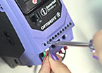
How do we do this in practice with a variable frequency drive? We have the PID controller (or just PI controller on E3 drives) built into the drive, so we only need a suitable transducer or feedback signal to control our variable. Like most engineering, if the basics are right the rest is pretty easy. Make sure that the feedback signal from the transducer is giving you the values you’d expect, and that as you speed up and slow down the motor it changes in a predictable way. Run the system open loop at first to check this. If the transducer signal is say 2.3 to 5.7V, you can scale the analogue input it is connected to accordingly. If the transducer voltage increases with increasing motor speed, fine; if it falls (maybe you’re working with a vacuum pump) then you need to change a parameter (P-43 on E3, P3-04 on P2 and Eco) to tell the drive to work that way round. You can also change the sources of the feedback and setpoint signals so the setpoint can come from a fixed, stored value for example.
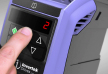
Once the transducer signal looks good you can enable the closed loop control in the variable speed drive and see what happens (P-12=5 on E3, P1-12=3 on P2 and Eco). It will probably stay nice and stable and not need any adjustments. If it’s not so stable, you can try adjusting the P and I terms; as previously mentioned, the D term isn’t usually needed. On E3 drives, P and I are adjusted by parameters P-41 and P-42 respectively. On P2 and Eco P3-01, P3-02 and P3-03 adjust P, I and D – all the closed loop parameters are P3-XX group.
One suggestion is to increase the P term until it oscillates, back it off a little and add a bit of I. It’s a bit of a black art, but don’t stray too far from the default settings and learn by experience. Controlling a narrow boat is probably harder, but at least you can stop at a pub and drown your sorrows.
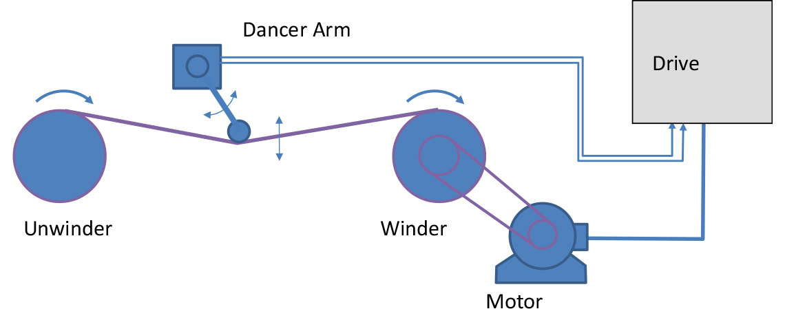
Closed loop control is often used for applications where temperature, pressure or flow rate need to be controlled, but there are many other applications; for example, maintaining tension in a winding system, shown in Figure 3. The dancer arm moves a potentiometer, which produces a signal indicating tension of the material being wound. This is fed back to the variable frequency drive which adjusts the speed of the winder to keep the tension constant.
On Eco and P2 drives there are several additional parameters which are sometimes useful. The ramps can be turned off to improve response, various limits may be set and if there is a problem like a burst pipe the drive can detect this and shut down, rather than run flat out and flood the place. The Eco drive has additional features such as cascade control and PID sleep function. These parameters are practical additions to a versatile closed loop controller.
Many variable frequency drive applications work in open loop or in conjunction with other control systems, but for simple applications the built in closed loop control can prove extremely useful.