Setting Setpoints
Article 26
In previous articles we’ve looked at how to set up and commission a variable frequency drive, and how we control it. Now we’ll look in a bit more detail at the setpoint, and the various ways that can be adjusted and set.
What’s the setpoint? Well, it’s the frequency that you want to be applied to the motor. So a setpoint may be 5Hz, 25Hz, 123.4Hz etc. We often talk about speed control with a drive, but in nearly all applications we are only controlling the frequency we supply to the motor. The speed will vary a little depending on the slip of the motor, which in turn depends on the load.
Of course, the motor speed will also depend on the motor construction – the number of poles. A four pole motor at full load will rotate at about 700rpm when a frequency 25Hz is fed to it; a two pole motor will be doing about 1400rpm.
The motor may not be running at these speeds for various reasons. Maybe it’s still accelerating or decelerating, maybe the drive is in current limit, or has tripped. But if it’s running normally, most of the time we aren’t interested in the actual speed of the motor, we just want the conveyer to deliver the package at the right speed, or the air to supply the amount of cooling we want.
We tend to talk about speed and frequency interchangeably, although they aren’t really.
However, if you want better speed control there are several options. Slip compensation will help. The drive monitors the load current, and as it has an idea what the motor slip is (you’ve told the drive something about the motor when you put the motor parameters in), so it can up the output frequency a little to compensate, as shown in Figure 1.
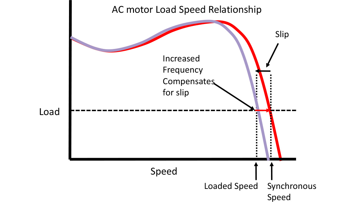
Simple really. Most Invertek drives will use some form of slip compensation if the motor speed (P-10 on E3, P1-10 on P2 and Eco) is set.
Vector control does it better. By modelling the position and speed of the motor, the drive knows what the motor’s doing, so it can adjust the frequency to control the motor to the setpoint speed, and indicate the true motor speed. That is, when a drive runs in Vector control, the indicated frequency is pretty much the true speed of the motor (Revs per second/pole pairs).
Finally, if you really need to know what the motor is doing, and control its precise speed, you can use an encoder. The encoder is fitted to the back of the motor and feeds a series of pulses back to the drive allowing it to control the speed exactly. Encoders are particularly good when working with hoists, cranes and lifts, because you can control the motor from zero speed at the instant the brake is released. Modern Vector drives can also do this pretty well though, without the expense of the encoder
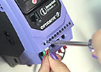
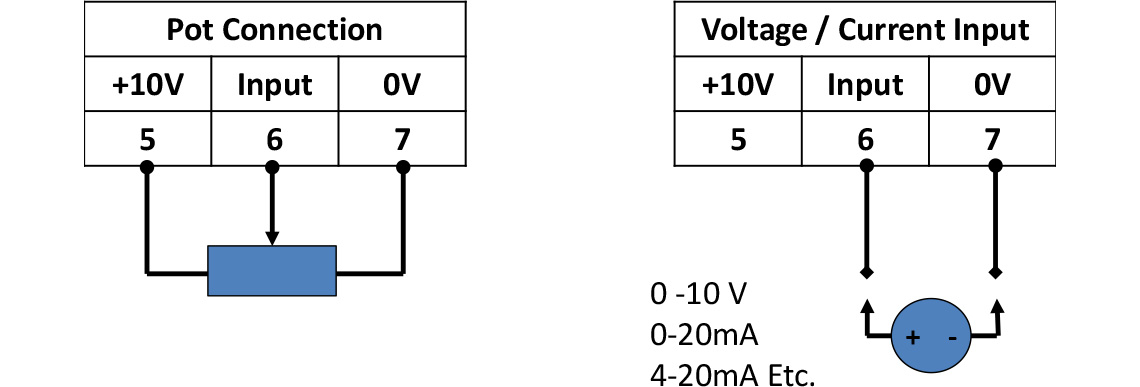
OK, back to the setpoint. The easiest way to adjust the setpoint is to apply a 0 to 10V signal to the appropriate input (on Invertek drives it’s terminal 6 with respect to terminal 7). If you don’t have a handy supply, terminal 5 offers a 10V output, so you can connect a potentiometer to 5,6 and 7. Easy.
Now adjusting the pot will change the input on terminal 6 between 0 and 10V, and the setpoint will vary (by default) between 0 and 50Hz (60Hz in US etc). If the drive is given a run command it will now increase the output frequency from 0Hz up to the setpoint, depending on the acceleration rate set on P-03 (P1-03 in Eco and P2).
But suppose we want to control the drive from a 0 – 20mA or 4 – 20mA signal? No problem, we can just change a parameter (P16 on E3, P2-30 on Eco and P2 drives). If you want the 4 – 20mA signal to raise an alarm or run at a preset speed if it falls below 3mA that can be set here as well. Inverted signals (10-0V etc.) and bipolar inputs (-10 to +10V) can be handled on some drives. Figure 2 shows the simple connections.
All this is fine if you have a pretty standard signal, but suppose you are working with an input that for some reason is 3 to 6V? Pretty unlikely, but it can happen, and tweaking the analogue input is also useful if you are using it in closed loop control as an input for a sensor. So many drives allow the analogue input to be rescaled (P-35 on E3, P2-31 on P2 and Eco) and an offset applied (P-39 on E3, P2-32 on P2 and Eco) for complete flexibility. The scaling and offsets apply to the current inputs as well as the various voltage inputs.
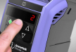
The setpoint doesn’t have to come from the analogue input. Full control can be handed to the built in keypad, and the setpoint adjusted using the ‘up’ and ‘down’ arrows. There are various options here to allow the drive to start at various speeds (previous speed, a preset speed, minimum speed etc.) to cater for all tastes. You can decide if the reverse button is active or not, as some machines don’t like going backwards.
Preset frequencies can be set up individually in different parameters (P20-23 on E3, P2-01 to 2-07 on P2 and Eco) and then selected as required via input terminals. So you can run the drive at slow, medium or fast as needed. The frequencies can be selected using the digital inputs, and you can even use binary encoding to select all fixed frequencies using two or three inputs for example. The preset frequencies can also be used for other functions, and can determine the start value in keypad control if needed.
If you’re controlling the drive via a serial interface, then the setpoint can be transmitted to it at any time, and updated as required.
Finally, as described in an earlier article, all Invertek drives offer the facility of master/slave operation (although E3 drives can’t be a Master) using a simple plug and play connection via the RJ45 port. In this mode of operation the slave drive simply mimics what the master drive is doing, so it derives its setpoint via the serial connection.