Zaawansowany przemiennik częstotliwości
Dedykowany do sprężarek BLDC, pomp ciepła i jednostek CDU
Teraz dostępny w 4 rozmiarach obudowy do 75A
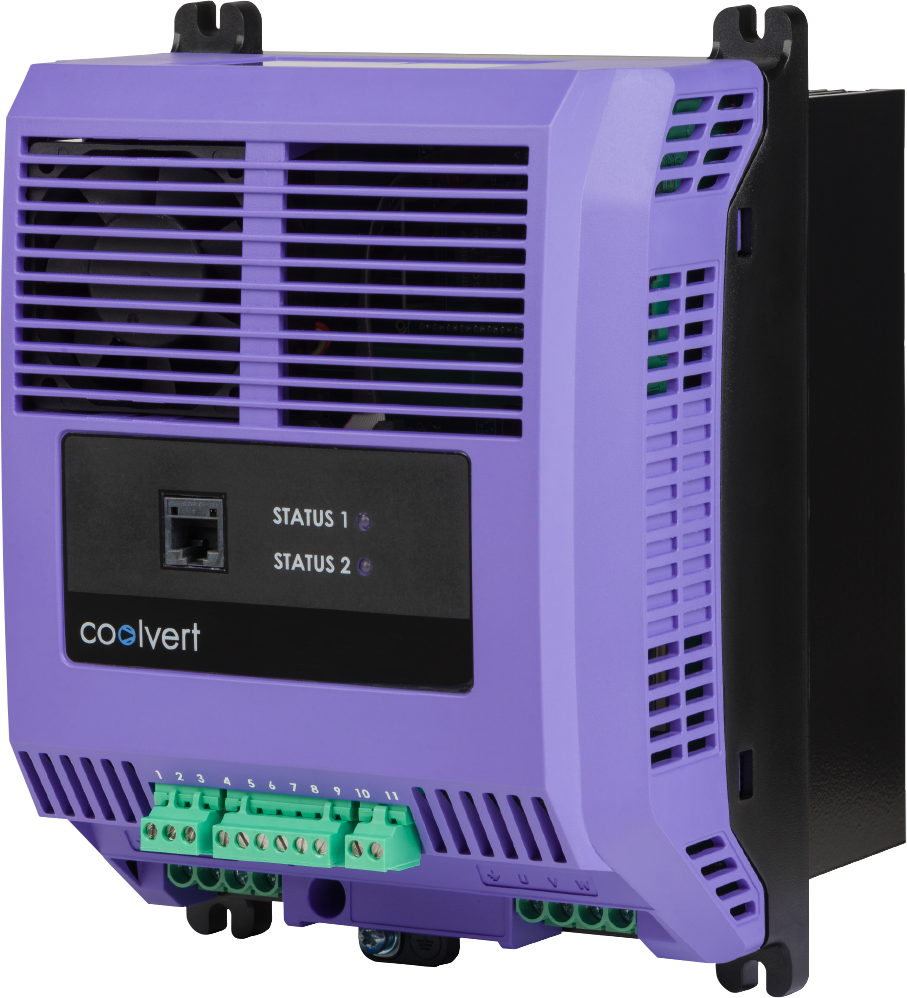
- Kompaktowy
- Wysoka wydajność
- Rozwiązanie globalne
Specyfikacja Optidrive Coolvert
| kW | HP | Amps | Size | Model Code |
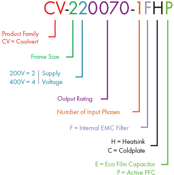
Product Family |
Frame Size |
Voltage Code |
Power Rating Code |
Number of Input Phases |
EMC Filter |
Heatsink/Coldplate |
Power Technology |
|||||
|---|---|---|---|---|---|---|---|---|---|---|---|---|---|---|---|---|---|
| 200 – 240V ± 10% 1 Phase Input |
1.5 | 2 | 7.0 | 2 | CV | - | 2 | 2 | 0070 | - | 1 | F | # | P | |||
| 3 | 4 | 12 | 2 | CV | - | 2 | 2 | 0012 | - | 1 | F | # | P | ||||
| 4 | 5.5 | 16.0 | 2 | CV | - | 2 | 2 | 0160 | - | 1 | F | # | P | ||||
| 5.5 | 7.5 | 20.0 | 2 | CV | - | 2 | 2 | 0200 | - | 1 | F | # | P | ||||
| 380 – 480V ± 10% 3 Phase Input |
5.5 | 7.5 | 14 | 2 | CV | - | 2 | 4 | 0140 | - | 3 | F | # | E | |||
| 7.5 | 10 | 18 | 2 | CV | - | 2 | 4 | 0180 | - | 3 | F | # | E | ||||
| 11 | 15 | 24 | 2 | CV | - | 2 | 4 | 0240 | - | 3 | F | # | E | ||||
| 15 | 20 | 30 | 3 | CV | - | 3 | 4 | 0300 | - | 3 | F | # | E | ||||
| 18.5 | 25 | 39 | 3 | CV | - | 3 | 4 | 0390 | - | 3 | F | # | E | ||||
| 22 | 30 | 46 | 4 | CV | - | 4 | 4 | 0460 | - | 3 | F | # | E | ||||
| 30 | 40 | 58 | 4 | CV | - | 4 | 4 | 0580 | - | 3 | F | # | E |
Model Code Guide
Rozmiar i masa
Heatsink Version (dimensions in mm)
NOTE: The Heatsink Version can be conventionally mounted on the backplate of a panel using the optional panel mounting kit (sold separately)

| A | B | C | D | E | F | G | H | J | K | ||||||||||||
|---|---|---|---|---|---|---|---|---|---|---|---|---|---|---|---|---|---|---|---|---|---|
| mm | in | mm | in | mm | in | mm | in | mm | in | mm | in | mm | in | mm | in | mm | in | mm | in | ||
| Size 2 | 226.3 | 8.9 | 215.2 | 8.5 | 201.4 | 7.9 | 165.3 | 6.5 | 144.8 | 5.7 | 182 | 7.2 | 177 | 6.96 | 71.7 | 2.82 | 104.4 | 4.11 | 104.4 | 4.11 | |
| Size 3 | 277.5 | 10.9 | 262.6 | 10.3 | 247.2 | 9.7 | 193.6 | 7.6 | 168.9 | 6.6 | 224 | 8.8 | 200.3 | 7.9 | 84.3 | 3.3 | 116 | 4.6 | 116 | 4.6 | |
| Size 4 | 310 | 12.2 | 336 | 13.3 | 364 | 14.3 | 239.5 | 9.4 | 150 | 5.9 | 291.5 | 11.5 | 230.6 | 9.1 | 98 | 3.9 | 133 | 5.2 | 133 | 5.2 | |
Coldplate Version (dimensions in mm)

| A | B | C | D | E | F | G | H | J | |||||||||||
|---|---|---|---|---|---|---|---|---|---|---|---|---|---|---|---|---|---|---|---|
| mm | in | mm | in | mm | in | mm | in | mm | in | mm | in | mm | in | mm | in | mm | in | ||
| Size 2 | 226.3 | 8.9 | 215.2 | 8.5 | 201.4 | 7.9 | 165.3 | 6.5 | 90 | 3.5 | 37.7 | 1.48 | 113.9 | 4.48 | 104.4 | 4.11 | 9.5 | 0.37 | |
Technical Specifications
| Parametry wejściowe | Napięcie zasilające | 200 – 240V ± 10% 380 – 480V ± 10% |
| Częstotliwość zasilania | 48 – 62Hz | |
| Współczynnik przesunięcia fazowego | > 0.98 | |
| Asymetria fazowa | Dopuszczalne maksimum 3% | |
| Początkowy prąd rozruchowy | < Mniejszy od prądu znamionowego | |
| Częstość załączeń zasilania | 120 / godzinę, nie częściej niż co 30 s |
| Parametry wyjściowe | Moc wyjściowa | 200V: 7.0A to 20A 400V: 14A to 24A |
| Przeciążalność prądowa | 130% przez 10 s | |
| Częstotliwość wyjściowa | 0 – 500Hz | |
| Acceleration Time | 0.01 – 600 seconds | |
| Deceleration Time | 0.01 – 600 seconds | |
| Typowa sprawność | > 98% |
| Warunki środowiskowe | Temperatura | Przechowywania: od −40 do 70°C Pracy: od −20 do 60°C |
| Wysokość n.p.m. |
Do 1000 m n.p.m. bez wpływu na parametry Do 2000 m n.p.m. maks. z UL Do 4000 m n.p.m. maks. (bez UL) |
|
| Wilgotność | Maks. 95% bez kondensacji | |
| Drgania | Zgodnie z EN61800-5-1 |
| Obudowa | Stopień ochrony | Front IP20 Rear (Through Panel Mounting) IP55 |
| Coated PCBs | Designed for operation in 3S2/3C2 environments according to IEC 60721-3-3 |
| Programowanie | Modbus RTU (RS485) | Modbus RTU on Pluggable terminals and through RJ45 port |
| PC Tools | PC Tools software for Diagnostics and parameter configuration (RJ45 port only) | |
| Klawiatura | Optional Remote Keypad with TFT display for diagnostic and programming | |
| Aplikacja na smartfon | OptiTools Mobile |
| Specyfikacja sterowania | Tryb sterowania | 200 – 240V ± 10% 380 – 480V ± 10% |
| Częstotliwość PWM | 4 – 32kHz | |
| Tryb zatrzymania | Zatrzymanie po rampie, Wybieg silnika | |
| Częstotliwość zabroniona | 2 skip frequencies, user adjustable | |
| Tryby sterowania |
Modbus RTU (RS485) Terminal Control Digital / Analogue Terminal Control PI mode Master / Slave Mode |
| Bezpieczne wyłączenie momentu obrotowego (STO) | IEC 61800-5-2:2016 | SIL 3 |
| EN ISO 13849-1:2015 | PL “e” | |
| EN 61508 (Part 1 to 7): 2010 | SIL 3 | |
| EN 60204-1: 2006 & A1: 2009 | Cat 0 | |
| EN 62061: 2005 & A2: 2015 | SIL CL 3 | |
| Independent Approval | TUV Rheinland* |
| Funkcje aplikacyjne | Regulator PI | Wewnętrzy regulator PI |
| Demagnetisation Protection | Configurable over-current trip threshold for greater protection against demagnetisation of the motor | |
| Start-up Profile | Three stage configurable start-up profile to ensure lubrication and increased compressor lifetime | |
| Start/Stop Blocking Features | Configurable Minimum On Time, Minimum off Time and Minimum Re-Start Delay to reduce oil migration and maximise compressor lifetime | |
| Serial Communications Loss Fall-Back Speed | The ability to configure the drive to run at a ‘safe’ speed in the even of a loss of serial communication. Can prevent total loss of operation whilst maintaining minimum process demands |
| Diagnostyka i serwis | Pamięć błędów | 3 ostatnie błędy ze znacznikiem czasowym |
| Rejestracja danych | Logowanie danych w sytuacji awarii na potrzeby diagnostyki: Prąd wyjściowy Temperatura napędu Napięcie szyny DC |
|
| Monitoring | Licznik czasu pracy kWH |
| Zgodność | The Coolvert product range conforms to the relevant safety provisions of the following council directives: 2014/30/EU (EMC), 2014/35/EU (LVD), 2006/42/EC (Machinery Directive), 2011/65/EU (RoHS 2) and 2009/125/EC (Eco-design) | |
| Design and manufacture is in accordance with the following harmonised European standards: | ||
| BSEN 61800-5-1: 2007 & A1: 2017 | Adjustable speed electrical power drive systems. Safety requirements. Electrical, thermal and energy. | |
| BSEN 61800-3:2018 | Adjustable speed electrical power drive systems. Part 3: EMC requirements and specific test methods (IEC 61800-3:2017). | |
| BSEN 61800-9-2:2017 | Adjustable speed electrical power drive systems. Part 9-2: Ecodesign for power drive systems, motor starters, power electronics and their driven applications – Energy efficiency indicators for power drive systems and motor starters (IEC 61800-9-2:2017). | |
| BSEN 60529: 1992 & A2: 2013 | Specifications for degrees of protection provided by enclosures | |
| UL 61800-5-1 | cUL Listed * cUR Recognised for the coldplate variants * |
|
| BSEN 61000-3-12: 2011 | Electromagnetic compatibility (EMC) - Part 3-12: Limits - Limits for harmonic currents produced by equipment connected to public low voltage systems with input current >16 A and ≤ 75 A per phase | |
|
BSEN 61000-3-2:2019 (single phase input variants only) |
Electromagnetic compatibility (EMC).Limits - Limits for harmonic current emissions (equipment input current ≤16 A per phase) | |
*Pending