
General Purpose Drive
Compare the Optidrive E Series
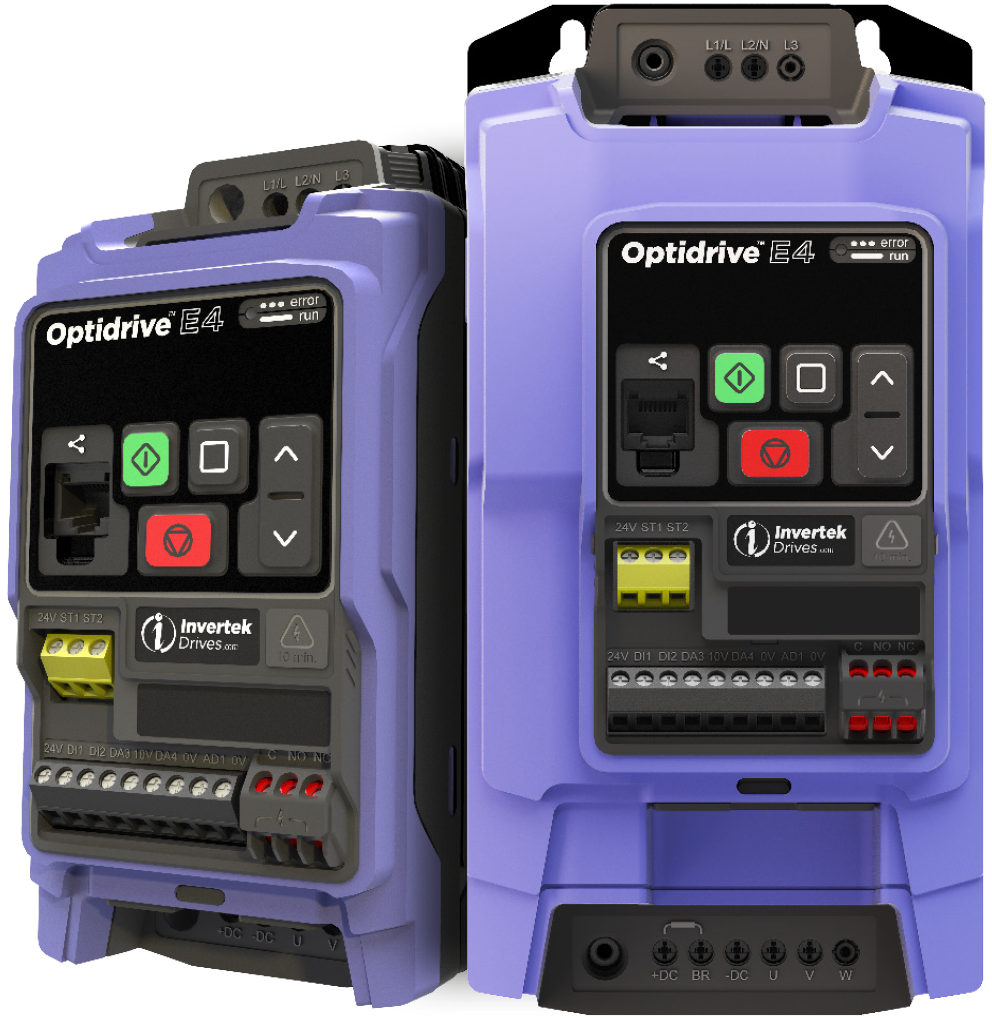
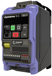
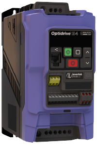
Optidrive E4 Specification
Size & Weight
| IP20 |
|---|
| Height mm (in) |
| Width mm (in) |
| Depth mm (in) |
| Weight kg (lb) |
| Fixings |
| Packaged Height mm (in) |
| Packaged Width mm (in) |
| Packaged Depth mm (in) |
| Packaged Weight kg (lb) |
| IP20 | Size 1 |
|---|---|
| Height mm (in) | 176 (6.93) |
| Width mm (in) | 82 (3.23) |
| Depth mm (in) | 136 (5.35) |
| Weight kg (lb) | 1 (2.2) |
| Fixings | 4xM5 |
| Packaged Height mm (in) | 165 (6.5) |
| Packaged Width mm (in) | 125 (4.92) |
| Packaged Depth mm (in) | 235 (9.25) |
| Packaged Weight kg (lb) | 1.2 (2.65) |
| IP20 | Size 2 |
|---|---|
| Height mm (in) | 222 (8.74) |
| Width mm (in) | 108 (4.25) |
| Depth mm (in) | 168 (6.61) |
| Weight kg (lb) | 1.7 (3.75) |
| Fixings | 4xM5 |
| Packaged Height mm (in) | 234 (9.21) |
| Packaged Width mm (in) | 144 (5.67) |
| Packaged Depth mm (in) | 260 (10.24) |
| Packaged Weight kg (lb) | 1.9 (4.19) |
Technical Specification
Input Ratings
Supply Voltage
110-115V -15%/+10%
200-240V -15%/+10%
380-480V -15%/+10%
200-240V -15%/+10%
380-480V -15%/+10%
Supply Frequency
48 – 62Hz
Displacement Power Factor
> 0.98
Phase Imbalance
3% Maximum allowed
Inrush Current
< rated current
Power Cycles
120 per hour maximum, evenly spaced
Output Ratings
Overload Capacity
Heavy Duty
150% for 60 seconds
175% for 2.5 seconds
150% for 60 seconds
175% for 2.5 seconds
Output Frequency
0-500Hz, 0.1Hz (high frequency firmware on request)
Typical Efficiency
> 98%
Ambient Conditions
Temperature
Storage: -40 to 60°C
Operating: -20 to 50°C (60°C derating)
Operating: -20 to 50°C (60°C derating)
Altitude
Up to 1000m ASL without derating
Up to 2000m maximum UL approved
Up to 4000m maximum (non UL)
Up to 2000m maximum UL approved
Up to 4000m maximum (non UL)
Humidity
95% Max, non condensing
Vibration
Conforms to EN61800-5-1
Enclosure
Ingress Protection
IP20 NEMA 1 with IP20 option kit
Programming
Keypad
Optional TFT remote keypad
Display
7 Segment LED
PC
Optitools Pro over RJ45 port or USB-C
Mobile Device
Optitools Pro over USB-C
Copy Stick
Over RJ45 Port
Control Specification
Control Method
Vector Speed Control, PM Vector Control (Auto back emf measurement)
Sensorless Vector Speed Control
V/Hz Speed Control Synchronous Reluctance
BLDC Control
LSPM
PMAREL Torque Control
Sensorless Vector Speed Control
V/Hz Speed Control Synchronous Reluctance
BLDC Control
LSPM
PMAREL Torque Control
PWM Frequency
4 - 16Hz Effective
Stopping Mode
Ramp to stop
Coast to Stop
Coast to Stop
Braking
AC Flux Braking
DC Injection Braking (Time, current & speed adjustable at start & stop)
Dynamic Braking (Size 2 & larger)
DC Injection Braking (Time, current & speed adjustable at start & stop)
Dynamic Braking (Size 2 & larger)
Skip Frequency
Single Point, User adjustable
Setpoint Control
Analog Signal
0 to 10 Volts
10 to 0 Volts
0 to 20mA
20 to 0mA
4 to 20mA
20 to 4mA
10 to 0 Volts
0 to 20mA
20 to 0mA
4 to 20mA
20 to 4mA
Digital
Motorised Potentiometer (Keypad)
Modbus RTU
CANopen
Modbus RTU
CANopen
Optional
EtherNet/IP, Modbus-TCP, Profinet, Ethercat frequency input up to 100kHz
Frequency Range
0-500Hz (2000Hz on request for IM)
Fieldbus
Built in
BACnet MS/TP
CANopen
Modbus RTU
Odd, Even, no Parity, 1/2 stop bits
Optional
Other
Modbus-TCP
Ethernet-IP
Profinet
Ethernet-IP
Profinet
I/O Specification
Power Supply
24Vdc, 150mA short circuit & current limit protected
10Vdc, 10mA short circuit protected for potentiometer
10Vdc, 10mA short circuit protected for potentiometer
Programmable Inputs
4 total,
2 Digital
2 Analog/Digital
2 Digital
2 Analog/Digital
Digital Inputs
8 – 30 Volt DC, from on-board or external voltage source
<4ms response time, NPN/PNP Logic
<4ms response time, NPN/PNP Logic
Analog Inputs
Resolution: 12 bits
Accuracy: ±2% full scale
Response: < 4ms Parameter adjustable scaling & offset
Accuracy: ±2% full scale
Response: < 4ms Parameter adjustable scaling & offset
Programmable Outputs
1 Analog (0-10V, 0-20mA, 4-20mA)/Digital (24Vdc)
1 Changeover Relay
1 Changeover Relay
Relay Outputs
Maximum Voltage: 250Vac, 30Vdc
Switching Capacity: 6A AC, 5A DC
Switching Capacity: 6A AC, 5A DC
Application Features
PI Control
Internal PI Controller
Standby / Sleep Function
Standby / Sleep Function
Fire Mode
Bidirectional
Select speed setpoint (Fixed/PI/Analog/Fieldbus)
Select speed setpoint (Fixed/PI/Analog/Fieldbus)
Common DC Bus
DC terminal access (Sz2 and larger)
Phase loss disable
Phase loss disable
HVAC Features
Spin Start
Variable Torque
Belt Failure detection
Variable Torque
Belt Failure detection
Pump Features
Low load detection (Dry Pump)
Maintenance & Diagnostics
Fault Memory
Last 4 trips & time stored. Logging Data prior for diagnostics:
Output Current
Drive Temperature
DC Bus Voltage etc
Output Current
Drive Temperature
DC Bus Voltage etc
Monitoring
Hours Run Meter
Real units (PSl, Bar, etc…)
Real units (PSl, Bar, etc…)
Input Phase Loss
Ripple and per phase measurement
Output Phase Loss
All 3 phases checked at each Enable (can be disabled)
Brake Protection
Brake resistor thermal overload
Standards Compliance
Low Voltage Directive
EN 61800-5-1: 2007 + A1:2017 + A11:2021
EMC Directive
EN 61800-3 : 2004 + A1:2012: 110V drives C3 5mtrs
200V drives C1 5mtrs
400V drives C2 5mtrs
200V drives C1 5mtrs
400V drives C2 5mtrs
Machinery Directive
EN 61800-5-2: 2017
EN ISO 13849-1:2023
EN ISO 13849-1:2023
Conformance
CE, UL, RCM, UL, UL 61800-5-1
Environmental Class
Conformal Coated PCBs. 2009/125/EC (Eco-design) & Regulation (EU) 2019/1781. 2011/65/EU (RoHS) modified by delegated directive 2015/863 : EN 63000:2018


