Electromagnetic Compatibility
Article 19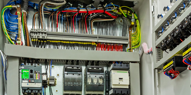
When there were crackles and pops on the wireless, or the TV turned to snow, people used to talk of ‘Radio Frequency Interference’ or RFI. Nowadays the problem of electrical and electronic systems interfering with one another can occur in many applications, and is referred to as Electromagnetic Compatibility – EMC.
Electronic machines are everywhere now, and operate at high frequencies (which are harder to contain) and high powers, so in some ways it’s surprising there aren’t more problems with interference, so what’s going on?
Any conductor carrying an electrical current emits electromagnetic radiation; the higher the frequency the greater the tendency for the energy to be transmitted from the conductor. Radio engineers soon learnt how to exploit this to transmit and receive signals using the simple electronics of valves, coils and capacitors. However, as more and more electronics was developed, it soon became clear that unintended signals were being transmitted - and received. Wires, and even printed circuit board tracks within control equipment were radiating (transmitting) unwanted signals to, for example, sensitive measuring devices, causing false readings. Perhaps worse, interference was making its way down supply or control cables, entering other equipment and causing malfunction. As electronic systems spread and took control in home and industry, the problem grew. Horror stories abounded, culminating in the (apocryphal) case of an aircraft crashing when the internal oscillator of a passenger’s radio interfered with the landing system.
As usual, engineers and equipment manufacturers reacted first, and legislation followed. Designers approached the problem in two ways. Firstly, they tried to prevent interference entering their own equipment; that is, they improved the immunity of the equipment to electromagnetic interference (EMI). Secondly, they worked on reducing the EMI generated by their product. Over time, electronic equipment, especially power products such as power supplies and variable frequency drives, sprouted filters on their inputs, and many detailed improvements in layout and shielding. This slow evolution has meant that most modern electronic machines now have the lowest emissions and highest immunity that can be achieved at reasonable cost.
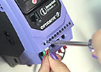
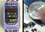
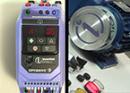
Slowly, regulations caught up. European legislation states that, although variable frequency drives do not have to meet particular EMI levels themselves, the equipment they are built into must comply with EMC Directive 2004/108/EC. In practice this means that the drive must be fitted with a filter, and that some care must be exercised when installing a variable frequency drive. The standards referred to in the directive set different levels of transmitted EMI for industrial and domestic applications. Other standards apply to medical, aviation and similar applications. All Invertek drives intended for use within the European Union are supplied with a suitable industrial filter built in.
So getting the variable frequency drive design and filtering correct is only part of the story; how it is installed is just as important. Most electronic controls operate without problem these days, but a poorly installed drive – or other equipment – can still cause interference, resulting in malfunctions which can be difficult and time consuming to sort out. So it’s important to follow a few basic installation rules to minimise this risk.
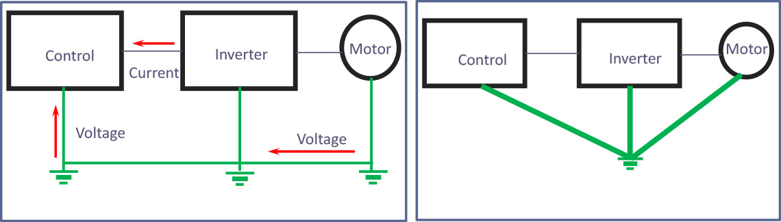
1. Good Grounding
Grounding is often necessary for safety reasons, but it is also important to minimise EMI. For effective grounding at high frequency and also to eliminate noise at low signal levels, ground connections should be short, thick, and to a common star point. Additional braided cable (which is better at high frequencies) may be used in some circumstances. Star point grounding isn’t always possible, but long, thin grounding cables are not a good solution.
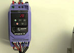
2. Screened or Armoured Cable.
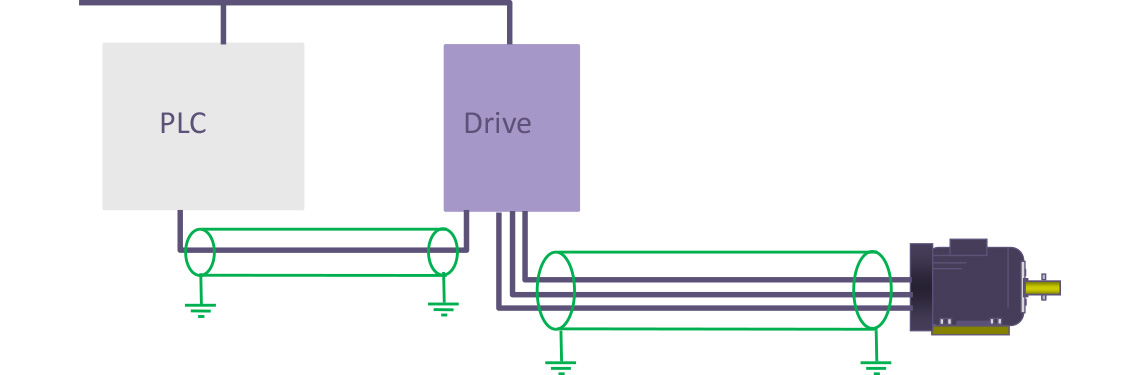
In earlier articles we saw that the output of the variable frequency drive is a nice sine wave current, but that the voltage waveform consists of high voltage square waves switching at a high frequency. The switching edges of these pulses generate even higher frequencies; these can cause serious EMI. Therefore it is always recommended to use screened cable (armoured cable is nearly as good) between the drive and motor. This encloses and contains the potential interference. Unscreened cable may work most of the time, but if it doesn’t you have an expensive rewire job, costing a lot more than the original screened cable.
Screened cable should also be used on signal cables, especially those carrying sensor signals which will be sensitive to EMI.
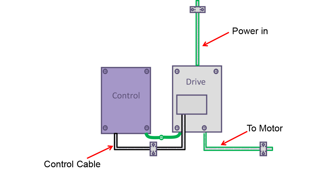
All screens should be well grounded where they come into the cubicle using suitable clamps. Screens should also be grounded at both ends; if interference problems go away when a screen is disconnected at one end, it’s a sign of circulating currents, probably caused by bad grounding. In this case, try to find the root cause of the problem.
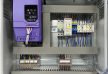
3. Separation and layout
The closer cables are to one another the more EMI can transmit from one to the other. A well planned cubicle will separate power and control signals, keeping the cables as far apart as practical, with cables crossing at right angles to minimise transmission. Plan the cubicle with EMC in mind; that way power and signal cables can be easily separated and star point grounding built into the layout.
All cabling should be kept as close as possible to a ground plane, such as the metal of the cubicle. This reduces the radiation from the wiring. Cable length should be minimised and large loops avoided. Pairs of cables (go and return connections) should be routed together (twisted pairs are ideal) as the EMI cancels.
4. Suppress Contactor Coils
When a contactor is switched, there may be a bit of arcing on the main contacts, but the actuating coil is a big inductor, so breaking the current will generate a significant spark – that’s how ignition circuits used to work in the days when you had a chance of fixing a dead car. The spark will create a flood of EMI at many frequencies, and can get into control circuits with ease. Variable frequency drives are protected from this, but a suppression circuit such as a Varistor, ‘flywheel’ diode or resistor capacitor network will stop the problem at its source.
Of course, you can save money and ignore the whole issue of EMC. These days you may get away doing that without problems. But even if you have to do a rewire only occasionally, or fly to site once and spend a couple of days babysitting a sporadic problem, you’ll still be in pocket if you follow a few simple rules and avoid callouts.
There are some very good explanations and guidelines on the internet. Search for “EMC installation guidelines” to find some readable, sensible recommendations.