Relays and Analogue Outputs
Article 24
The main purpose of a variable frequency drive is to control the speed of the motor connected to it. However, the drive also provides many features to help control and monitor the drive and overall process performance. The output relays and analogue output function are examples of this.
Nearly all drives are fitted with at least one output relay. Invertek’s E3 has one relay, Eco and P2 drives have two. Although relays are simple electromechanical devices, they have the advantage they are easy to understand and connect up, and offer a high level of isolation, so EMC problems and damage to the drive are unlikely. Of course, it is important not to exceed the relay rating. Relays on Invertek drives can switch up to 250V AC (30V DC) at 5A; other drives may have different ratings.
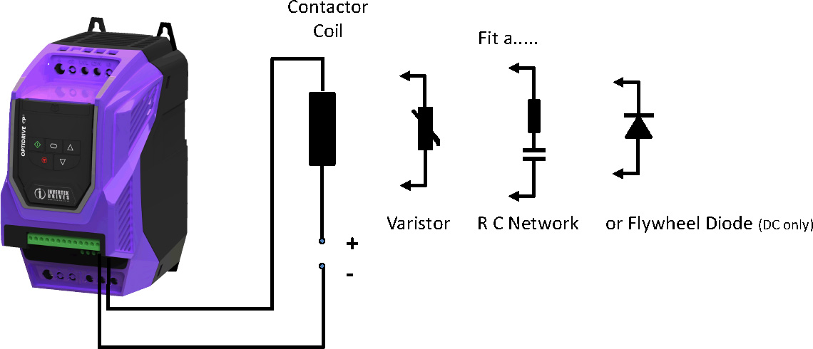
In any case, remember to fit suppression components, especially if you are switching a contactor coil or similar. Arcing in the relay, caused by switching an inductive load such as a coil, will quickly damage the relay contacts and may cause interference with the drive, although the drives are tested to ensure this doesn’t happen! Figure 1 shows the various suppression components available and where to connect them.
The relays can be programmed (by setting parameters) to respond to many conditions. The simplest, and the default setting, is ‘drive healthy’. Put another way, the relay is energised when the drive isn’t showing a fault. Usually the contacts that are closed in this healthy state would be connected back to an alarm monitor, and if they open, or the wire breaks, the supervisory system would detect this and react accordingly. The reverse state – i.e relay energised when a fault is present can also be programmed on some drives.
Other useful settings for the relay include ‘drive running’ and ‘drive at setpoint’ (i.e. running at the target speed). Both these indications can help in control systems where other processes can start once the drive is seen to be doing its job.
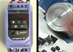
A particularly neat feature of Invertek drives is the ability to energise the relay at a selected threshold of frequency or current (for P2 and Eco drives, Torque as well). So maybe in a mixer, if the beaters are over a certain speed, the operator must check for foaming - the relay can turn on a light to show this. Or if the current or torque reaches a certain threshold, the mixture has thickened and is ready, again the relay can indicate this is the case. The threshold is set as a percentage using a separate parameter. On E3 drives, the relay can be set to close or open at the threshold (the hysteresis is set using another parameter); on P2 and Eco drives separate upper and lower thresholds can be set, so hysteresis can be set easily.
P2 and Eco drives have many special features, so additional relay functions are provided to support these. The P2 relay can be set up to control an electromagnetic brake (be sure to use a separate contactor to switch the brake coil, and suppress it!) in hoist mode, such that it releases and engages the brake to suit crane or hoist operation (see article: Cranes, Hoists and Elevators). The Eco drive includes a Fire Mode function, and the relay can show when Fire Mode is active. The relays are also used to enhance some of the Eco features such as Pump Staging and Overload Detection. On both drives, the status of the STO inputs can also be monitored by the relay (see article: Safety and Safety Inputs). Other settings can be used to indicate maintenance needs (for example, if bearings need greasing every 50 hours), and the PID error can be monitored to ensure correct closed loop operation.
The relay on the E3 has two connections available; the normally open and common contacts of the relay. The Eco and P2 drives have all three connections accessible on one relay, (normally open, normally closed and common) but just two on the second relay.
The specialist Elevator drive also has two relays, and includes functions to suit elevator operation.
The other useful output usually provided on a variable frequency drive is an analogue output. Invertek’s E3 drive has one, while the P2 and Eco have two outputs. These may be configured as 0-10V (the default setting) or on P2 and Eco drives formats such as 0-20mA, 4-20mA may be selected.
The analogue output can be set up for analogue or digital operation. In digital operation, the analogue output switches between 0V and 24V to indicate conditions in the same way that the relays work. So ‘Drive Healthy’ or ‘At Target Speed’ etc. may be indicated.
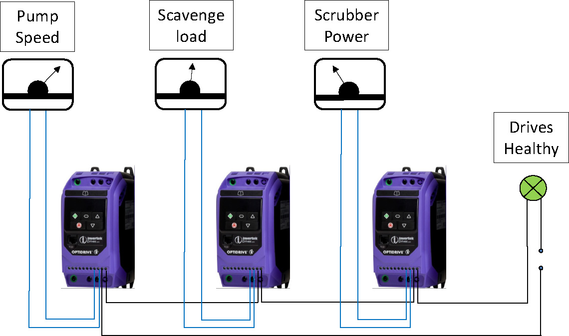
In analogue operation, values such as output frequency, current or power may be signalled, so these values can be monitored by an external system, or simply with a meter. The P2 and Eco drives will also show torque and PID output if required. Figure 2 shows how the relays and analogue outputs can be connected to provide simple monitoring; of course, they can also be connected to a control system such as a PLC.
The analogue output can be used to control other drives or equipment directly. For example, if the analogue output of one drive indicates the motor torque, a second drive may be run in torque control and connected to this. Then both drives will run with the same torque, sharing the load. This is more easily done using Invertek’s Master Slave mode, but the principle applies to all drives.
Remember that the analogue output is not isolated, so follow good EMC practice. In particular, take care when connecting to other equipment over long distance. Slight differences in grounding potentials will lead to false readings and possible damage. That’s the great thing about the output relays; the contacts are isolated.
Of course, the drive may also be monitored over a serial link connection, in which case the read only parameters can supply lots of information about the state of the drive.