Vector Control
Article 13
When a drive salesman tries to sell you a variable frequency drive the words ‘Vector Control’ will sooner or later come up. Earlier articles here describe how vector control is needed to work with Permanent Magnet motors and similar machines. So what exactly is vector control, and why is it ‘good’?
Well, let’s go back to basics. In the first article we described how an induction motor’s speed is controlled by the applied frequency, and how the flux – which allows torque to be produced – is dependent of the applied voltage, which produces a magnetising current in the stator. Now, in order to keep the optimum flux in the motor, a non vector drive will maintain a linear relationship between voltage and frequency; that is, as the frequency is reduced from the nominal value, the voltage is reduced in proportion. So 400V at 50Hz becomes 300V at 37.5Hz then 200V, 25Hz etc. Minor variations on this, for example, by increasing the voltage at low frequencies to overcome losses, are common practice. The basic control of a voltage to frequency (V to f) drive is shown in Figure 1.
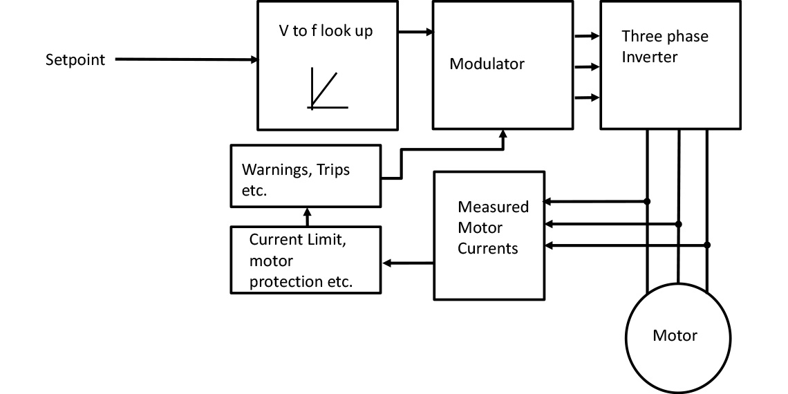
The modulator converts the voltage and frequency demand into the necessary pulses to drive the IGBTs in the inverter. The measured currents are used to protect the motor and drive by reducing the frequency or tripping the drive as required.
However, simply maintaining the V to f relationship doesn’t always give ideal performance. Motor characteristics vary with temperature, and it gets difficult to get the flux levels right at low speeds. So drive manufacturers will try to measure the magnetising current (the flux producing current, set by the applied voltage) and adjust the output voltage accordingly, rather than relying on the linear relationship. This helps a little, but for precise control, especially at low speeds, flux and torque generating currents must be measured and controlled in real time. So as the motor and applied phase voltages rotate, the position and magnitude of these currents are important – that is, they are vector quantities.
So now, instead of having a drive that produces a certain voltage and frequency at a particular setpoint, we try control the motor flux and torque directly, and adjust that control continuously to give the setpoint we desire. The (simplified) control system of a Vector drive is shown in Figure 2.
.jpg)
You can see from Figure 2 that the setpoint demand from the user is converted into a speed and then a Torque demand, as well as a field then Flux demand that is part of the vector control system.
To do all this, we need some pretty complicated mathematics, as well as accurate current measurement. We also need to know the characteristics of the motor we are controlling.
We can do the maths now with the powerful microprocessors that are available. We can also measure the output (i.e. motor) currents pretty accurately with Hall Effect devices. These features used to make vector drives more expensive, but these days add little to the cost of a variable frequency drive.
If you compare Figures 1 and 2 you can see how much more complex vector control is.
In order to determine the characteristics of the motor we rely on the user programming the drive with the correct information. By setting the correct value of motor current, voltage and power factor into the appropriate parameters, the basic information is given to the drive. However, additional information can be obtained by running an ‘Autotune’, and most vector drives will ask the user to run this when vector control is selected. In a few seconds the drive measures additional factors such as primary inductance and stator resistance, which will help build an accurate model of the motor, making vector control much easier.
Incidentally, the drive also takes into account the temperature of the motor during operation (calculated from the motor information and the load) as this affects many of the motor characteristics, so it is important to make carry out the autotune on a cold motor.
In the past, for good, reliable vector control, an encoder was recommended to give precise speed, and therefore rotor position, information. These days, with faster and improved mathematical modelling, an encoder is not so necessary. However, in some applications such as elevators and cranes it is still preferred. If no encoder is fitted, the drive will use the motor model instead to calculate the speed and position of the rotor.
The drive now controls the motor speed not by setting the output frequency directly (like a V to f control), but by controlling the motor torque and flux. So now the setpoint from the operator or PLC is converted into a flux and torque requirement as shown in figure 2. In other words the drive says “Based on the knowledge of the motor, how much torque and magnetic flux do we need to maintain the speed that’s been requested?” Because the drive is controlling the torque and flux directly, the performance of the drive is improved compared with conventional V to f operation. The drive responds better to sudden loads, is generally more efficient, and can more easily control different types of motors such as the Permanent Magnet and Synchronous Reluctance motors described in the previous article. The speed regulation is much better, as slip is automatically accounted for.
Figure 2 also shows that the output currents are monitored inside the drive and spilt into the torque and flux generating parts. These measured values are fed back into the torque and flux controllers so we have closed loop control of these currents, complete with summing points, gain etc. in the same way as other closed loop controllers (see an earlier article on closed loop control).
Because we measure all three currents, these need to be transformed and split into one flux current (i.e the magnetising current) and one torque (i.e load) current. These mathematical transforms are also used to convert the flux and torque demanded currents (from the setpoint and the summing points) back into three separate phases and then into the modulation signals that drive the power part of the inverter.
You’ll also notice that the estimated speed (calculated from the flux and torque currents and the motor model) is fed back in a third closed loop, this time controlling motor speed.
So the Vector Control system requires a lot of measurements and calculations, and includes three closed loop controllers. In the early days of vector control it proved hard to stabilise everything, and some drives proved difficult to set up and operate reliably, especially without encoders. These days better understanding of motor models have made Vector control simple and reliable to use.
Vector Control offers the advantages of better speed holding, better response to sudden load changes as well as greatly improved torque at low speeds. Motors often run more efficiently – and therefore cooler.
Invertek have always offered simple, effective vector control which is easy to set up. The P2 drive now offers comprehensive vector control features such as torque control and excellent low speed torque capability. The E3 drive includes a simplified vector control to improve performance.
With any drive, remember to set the correct motor parameters and follow the set up procedure. This is particularly important when working with permanent magnet, synchronous reluctance and similar motors. Don’t worry, there’s plenty of help available, including application notes on the website.