Power Factor, Form Factor and RMS
Article 23
Back to basics; no, not a political catch phrase, but a clarification, I hope, of how currents are measured in motors and variable frequency drives.
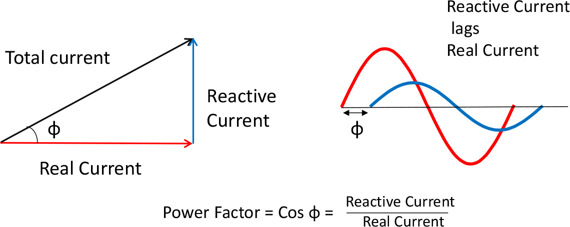
In the past, when the electricity grid supplied incandescent lights, heaters and motors, the power stations supplied a nice sine wave voltage, and the loads took a nice sine wave current. Everything in the system was designed to handle this waveform, which is ideal for transforming up (to distribute efficiently) and down (for end use). There was a minor difficulty, and that was that electric motors, and to some extent the transmission systems themselves, drew a magnetising current as well as a load current. Now a magnetising, or reactive current lags the applied voltage by 90 degrees, and although this current flows back and forth in the cables, it doesn’t do any useful work, and it isn’t normally metered for small users. But all the cables, transformers and generators need to be rated for this extra current, so the concept of power factor was born. This is the ratio of total current to reactive current. Power Factor is also referred to as Cos φ (phi), as this is the ratio when you draw the currents as a vector triangle, (Cos = Adjacent/Hypotenuse) shown in Figure 1.
If we multiply the currents by the voltage (same for both currents) it is the ratio of the Real Power to the Apparent (total) Power.
Power Factor is usually lagging (current lags voltage) but if the load is capacitive, a leading power factor can occur. By adding capacitance to the circuit, the lagging power factor can be corrected and there is less ‘unused’ current flowing around and wasting energy. Large electricity consumers, who are metered on real and apparent power, use power factor correction equipment which switches capacitors in and out of circuit – sometimes a source of transients and interference. Power stations can ‘motor’ generators to create a capacitive load and correct the power factor of the grid.
If you buy a IEC motor, the power factor (pf) or Cos φ is stated on the rating label. Remember this is the power factor when the motor is running direct on line rather than from a variable frequency drive. It is also the full load power factor, which will become worse (i.e. more lagging) when running at part load. (The magnetising current is the same, but the load current is less).
If you buy a NEMA motor, the efficiency of the motor may be stated instead of, or as well as the power factor.
Small motors have a poor power factor (maybe 0.7); larger motors are better. The lower the power factor, the more reactive current is flowing in and out of all of the circuit, so the greater the losses, meaning larger cables, transformers etc. are needed. So everyone is interested in keeping the power factor close to unity.
All this is fine when you are working with linear loads like mains fed motors which draw sine wave currents, but as we’ve seen earlier, drives don’t do that. Neither do televisions, laptops, LED lights etc. They all have rectifiers at the input, which take a chunk of current at the peak of the sine wave. So the power factor is pretty good, because the current is in phase (i.e not lagging or leading) with the voltage. But that doesn’t help when it comes to assessing the heating effect (in the cables, fuses or whatever) of the waveform. We need a better measure.
Root mean square is a better indication. RMS values take account of the waveform shape and the heating effect of that waveform. Figure 2 shows a simple illustration.
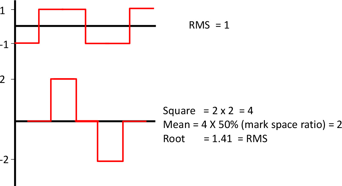
For each waveform, the current supplied is the evidently the same, but if we square the value of the current, then average that value, and take the square root, you can see the RMS of the more irregular waveform is higher, and the heating effect of the peak current is much greater than the simple square wave. Remember the heating effect is proportional to the square of the current (i2R), so the RMS value reflects that. Unfortunately the current waveform of a rectifier circuit approximates to the ‘peaky’ current, and as more and more rectifiers are added to the supply system, distortion creeps in. Of course, the network companies do all sorts of tricks to maintain sine wave current – and therefore a sine wave voltage, but the battle continues. We’ll talk about harmonics in another article, but back to RMS.
RMS values are nearly always used to state AC waveform values, as the simple average of an AC waveform is zero.
The ratio between the RMS of a waveform and the absolute average (i.e the ‘rectified’ average) of the waveform is known as the form factor, and is a convenient way to refer to ‘distortion’ of the waveform as well as its heating effect.
So let’s summarise before it gets to confusing.
- Power factor tells us about the phase shifts in sinusoidal waveforms and the reactive current when the load includes a magnetic (i.e. inductive) component.
- RMS is a measure of a waveform, usually AC, which gives a useful value that also indicates the heating effect.
- Form factor is a simple way of showing the degree of distortion of the waveform.
What does this mean for motors and variable frequency drives? Well, the motor still draws magnetising current and therefore has a power factor less than 1.0, as stated on the rating plate. The drive must supply the total current; the vector sum of the magnetising current and the load current, so although we rate the drives in kilowatts (or horsepower) to conveniently match motors, we still need to supply that extra current. The drive designers take this into account when rating the drive; if in doubt, check the current ratings of the drive and motor.
But the motor power factor isn’t reflected at the input to the drive. The drive’s rectifier input has a pretty good power factor, certainly compared with a direct on line motor, so it doesn’t particularly contribute to poor power factor problems in your factory or machine. But the power factor is pretty meaningless for a non sinusoidal waveform anyway. However, the form factor (and therefore the RMS value) of the current is not so good. Figure 3 shows the typical input waveforms of single and three phase rectifiers at the front of a drive.
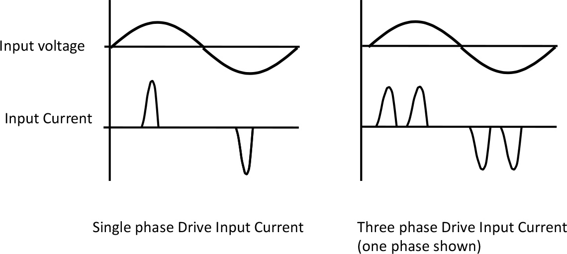
As all the current to the drive is carried in these short peaks, the drives RMS input current is quite high compared to the output current, and relatively heavy cabling and circuit breakers are needed.
So a drive will improve the power factor compared with a direct on line motor, but will draw non sinusoidal currents with a not so good form factor. Larger drives, and some specialist drives have power factor correction (PFC) front ends which draw sine wave currents and in some cases will regenerate. All this comes at a cost of course.