Setting up a Variable Frequency Drive
Article 6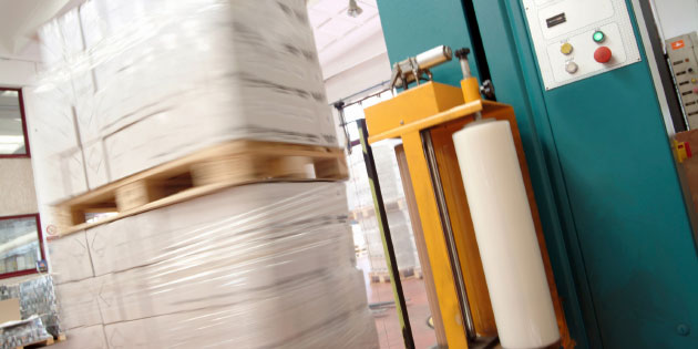
In the last article we selected and installed our variable frequency drive. Now we’ll look to commission it – that is, run it up and check it out.
In the last article we commissioned the drive, and hopefully got the motor turning. Now we need to adjust the settings to suit the motor and application. As previously explained, the settings in the drive are controlled by parameter values. Invertek variable frequency drives have thirteen basic parameters which allow the drive settings to be optimised for most applications. We’ll look at the additional parameters for specialist applications later.
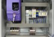
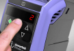
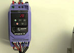
The parameters can be adjusted via the built in control panel in conjunction with the display. This may consist of a simple seven segment display, or a text display with more information. Either way, a long press on the navigate button will show a parameter number; you can then scroll to the parameter of interest using the up and down arrows, press the navigate button again to see the value, and use the up and down arrows to change it; then back out with the navigate button again. Sounds a bit confusing? It’s explained in the handbook, and you’ll get the idea once you’ve played around a bit (you won’t break it).
So once you’ve mastered changing parameters, what do you want to set up? Probably the most important parameters in this basic group are the motor parameters, P-07, P-08, P-09 and P-10. (On Eco and P2 drives these basic parameters are numbered P1-07, P1-08 etc.). With these parameters you tell the variable frequency drive the details of the motor you are using. This allows the drive to optimise control of the motor and, more importantly, protect the motor. By knowing the rated motor current the drive can calculate the heating effect of the actual current while the motor is running, and if necessary raise a warning or trip the drive to prevent motor damage. Other parameters here will tell the drive the voltage and frequency the motor works with, and enable the drive to choose the best voltage at a particular frequency. Finally, by telling the drive the rpm of the motor (at the nominal motor frequency) the display can show the calculated motor speed. In summary:
P-07 Motor Rated Voltage. This probably doesn’t need changing if you’ve bought the right variable frequency drive
P-08 Motor rated Current. Setting this will ensure the motor is protected by the drive.
P-09 Motor rated frequency. Again, this is probably OK.
P-10 Motor rated speed. Setting this to a value above zero will change all frequency displays from frequency to RPM.
So now the drive is nicely matched to the motor, you can think about matching it to the load and application. Parameters P-01 and P-02 (P1-01 and P1-02 on P2 and Eco) set the maximum and minimum output frequency. Default (Factory) settings are 50Hz (or 60Hz in countries that have that supply frequency) and 0Hz. Change the maximum frequency with care. When you take a motor above its nominal frequency, the maximum torque begins to reduce, also there may be bearing and other problems. Change the minimum frequency maybe if you are working with a pump or fan, which don’t do much at low speeds, or just to suit your process. If in doubt, leave at the defaults.
P-03 and P-04 set the acceleration (Ramp up rate) and deceleration (Ramp down rate) values that you’ll see when you start and stop the drive, or when you change the demanded speed. The acceleration rate is defined as the time taken to ramp up from 0Hz to P-09 the motor rated frequency; the deceleration rate is, of course, the opposite. The acceleration rate will be limited by the inertia of the load and motor, as well as the load itself. Don’t select a fast acceleration rate with a big fan for example; the drive may trip on overcurrent as it tries to speed up the high inertia. Rapid accelerations are fine for small machines of course. Fast deceleration time also cause problems; the inertia energy from the load may come back to the variable frequency drive and cause overvoltage trips. More on this later, but maybe just stick with nice slow rates for now. The default settings here are 5 seconds, but on higher power P2 and Eco drives much longer settings are used, reflecting the high inertias expected.
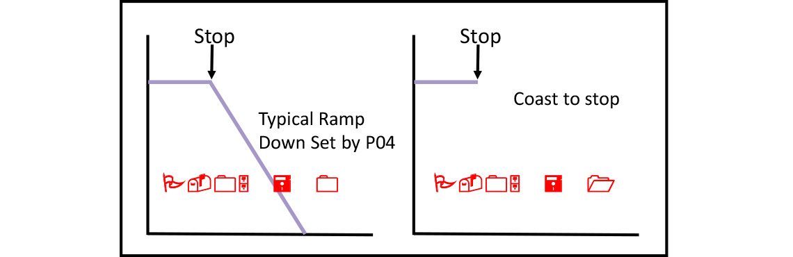
Parameter P-05 is all about stopping. Normally when you stop a variable frequency drive the frequency is reduced down to 0Hz at the deceleration rate set in P-04. This is good as you know when the motor stops. However, it may be more convenient to simply switch off the drive immediately the stop command is given; this is useful if the load has high inertia (it avoids the problem of regeneration and overvoltage mentioned earlier) or if you want to apply a brake for example. The default setting of P-05 = 0 gives the ramp down; changing this to 1 gives you the ‘coast to stop’ condition – the motor and load may coast for some time in this case. Another couple of settings allow the use of an alternative deceleration rate. Figure 1 shows the first two options.
In this basic parameter set this just leaves a few other parameters. P-06 is an energy saving function that, when enabled (P-06=1) reduces the magnetising current when the drive is running at low loads. Worth switching on, unless you’re expecting to deal with sudden load changes, in which case the drive’s response is a little delayed.
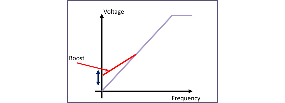
P-11 is a voltage boost parameter. At very low speeds, the motor theoretically doesn’t need much voltage, but in practice a small increase in the voltage will overcome losses and stator resistance etc. If you need torque at low speed (to get a conveyer started for example) try increasing P-11 a little. Too much and you may saturate the motor, or cause it to overheat. The handbook suggests some typical values. Figure 2 shows how the boost changes the voltage.
P-12 is a bit more complicated; it is about how you want to control the drive. The default setting (P-12=0) here is via the control terminals, as described earlier. A simple alternative is to use the keypad on the front of the drive (P-12=1 or 2). Other possibilities here are to use a serial communication system such as Modbus (P-12=3 or 4) or Can open (P-12=7 or 8). Another common application is to use the drive in closed loop control (P12=5 or 6).
A really neat setting (P12=9) is to put the drive into slave mode and control the drive from another master drive via a simple bus connection.
We’ll cover all these features in later articles; for now let’s stick to the simpler adjustments.
Finally P-13. On E3 this allows you to select your application. It’s a simple way of optimising the Voltage to frequency relationship for constant torque (industrial mode) or variable torque (Pump or Fan mode) applications. Fan mode also turns on the spin start function – more on this later. P1-13 in Eco and P2 is different here (for historical reasons) and sets up the digital inputs; we’ll look at that later as well.
This covers all the Basic parameters settings; for many applications you won’t need any more, but if you do, setting P-14 to the appropriate pass code will allow access to more parameters. In the next article we’ll look at some more parameters and features.