Warnings, Trips, Faults and Failures
Article 10
If we’ve read the handbook, selected, installed and set our drive up correctly, we may never see any warnings, trips, faults or failures. But sometimes things go wrong, so in this article we’ll look at what can happen to a variable frequency drive which stops it doing its job.
Of course, the worst thing that can happen to a drive is that it fails completely. This is a pretty unusual event these days as manufacturers have really got their quality and testing systems sorted. Power semiconductors are a lot more rugged as well, and many failures are down to issues such as contamination (with dust or liquids getting into units designed for cabinet installation) or misuse - connecting the input to the output for example. In any case, a variable frequency drive will try very hard to protect itself, either by tripping (turning off) or continuing to run but raising a warning.
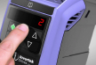
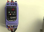
So let’s look at warnings first. On an Invertek drive, a warning will be indicated by flashing the decimal points in the display. A relay can also be programmed to indicate a warning or trip. When a warning is present, the drive will continue to run, but if the problem persists or gets worse, it will trip. When the drive trips, it stops immediately and shows the fault code in the display. The relevant fault codes are shown in [square brackets] in the descriptions below.
Usually a warning will be raised when a variable frequency drive, or the motor it’s controlling are overloaded or overheated. In the case of a motor, the drive will calculate the temperature of the motor based on the size of the motor, the square of the motor current, and the time it’s been running. This is often called an ‘i squared t’ warning. If the overload continues and the drive calculates the motor is getting too hot, it will trip [I_t-trp]. The drive maintains a log of trips in the read only parameters (P00-13, P0-13).
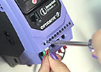
The trip calculation is dependent on the motor current that has been set in the inverter – in P-08 or P1-08. As this tells the drive the motor size and rating it should be set correctly to ensure proper motor protection. Occasionally it may be necessary to adjust this value if there is nuisance tripping.
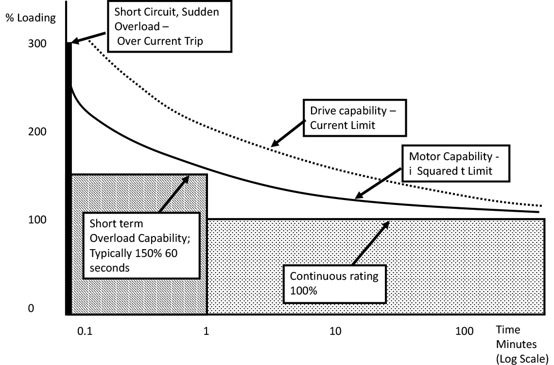
The variable frequency drive is protected in the same way. The drive is designed to operate for a short time in overload (for example, 150% load for 60 seconds), but sooner or later the drive will limit the current by reducing output frequency (and showing a warning) and eventually switch off to protect itself.
If the output current of the drive rises very rapidly, maybe due to a short circuit or stalled motor, the drive will switch off instantly – an over current trip [O-I].
In general, short term overload of the motor or drive, such as during acceleration, is fine, but will only be permitted if there is no danger of permanent damage. Figure 1 shows the operating envelope of the drive and motor with respect to time, and the trip and warning levels.
Variable frequency drives will get warm (due to internal losses) during normal operation. As the temperature increases, the drive will switch on the internal fans (fitted on all but the smallest drives) to maintain cooling. This usually maintains the temperature to a safe level, but if the ambient temperature is too high (for instance, in an enclosed cubicle or in a hot factory in the tropics) or if the airflow is limited (by a blocked external filter, or dirt and dust build up) then the internal electronics may begin to get hot. Fortunately, the drive detects this and will raise a warning. It may even reduce its switching frequency to reduce losses, but if the problem persists it will trip [O-t]. The temperature of the internal heatsink and power components is usually monitored as well.
If the drive gets too cold it will also trip – or not start – due to under temperature; semiconductors tend to get a bit sluggish below -10oC [U-t].
Warnings and trips may also be caused by over and under voltage on the internal DC link of the variable frequency drive. In either case, there’ll be a warning at a certain value, and if the voltage continues to rise or fall, the drive will trip.
Under voltage occurs if the supply is below the specified value for the drive, or more usually if the power to the drive is disconnected while the drive is running. It’s quite common to find the fault log of a drive full of under voltage trips as a result of this [U-volt].
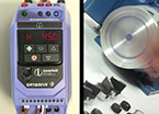
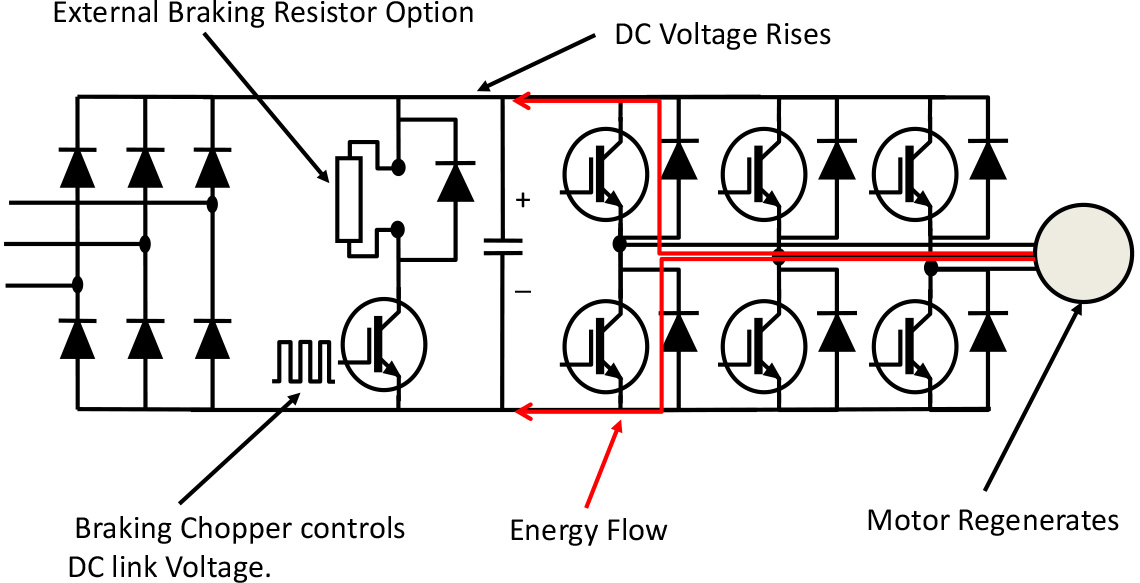
Overvoltage can be caused by the supply rising too high, but is more likely to be the result of regeneration [O-volt]. This takes place if the load starts feeding energy back to the motor, rather than the motor driving the load. A crane or elevator lowering a load, a downhill conveyer, or too rapid deceleration of a high inertia load- such as a fan - will cause this. If the inverter continues to supply voltage to the motor, then the motor will generate and feed energy back to the drive. This will increase the DC link voltage and may cause failures if the voltage goes too high. The drive will trip with overvoltage if necessary to prevent this happening. Once the drive is tripped, the magnetic field in the motor collapses and it stops generating and coasts. There are ways of preventing overvoltage when the motor is generating, such as using a braking resistor, using a longer deceleration, or just coasting the motor to a stop instead of decelerating (P-05 or P1-05 = 1). Incidentally, if there is over current or overload in the braking resistor circuit that will trip the drive as well [O-b][OL-br]. Figure 2 shows how the energy flows back to the variable frequency drive and causes overvoltage.
Other faults tend to be related to settings. If the parameters of the drive are reset by the user, then that’s indicated as a fault [P-deF]. If the user programmes one of the inputs as an external trip input, then at the appropriate input level (usually low or open circuit) the drive will trip [E-triP]. Inputs can also be programmed to be connected to a motor PTC (a motor PTC is a component embedded in the motor windings that changes resistance suddenly at a particular temperature, hopefully just below the insulation failure temperature. Often PTCs are embedded in each stator phase.) If the resistance rises above the threshold (or the wire drops off), the variable speed drive trips [F-Ptc].
If you’re using a 4-20mA signal to control the drive, you can set it up so you get a fault if the wire breaks [4-20 F].
On some drives phase loss on the input (for three phase input drives) or output will be detected and the drive will trip [P-LOSS][Out-F].
There are other faults, but these usually related to specific settings, communications etc.
A common ‘fault’ with P2 and Eco drives is forgetting to connect or bridge the Safe Torque Off inputs; the drive is then disabled [INhibit].
In conclusion, if a variable frequency drive is properly installed and set up, you are unlikely to see any faults or warnings. If you do, the drive is probably protecting itself or the motor from damage. The manual lists the different faults and their possible causes.