Variable Frequency Drive Selection and Installation
Article 4
In the last article we looked at the practical construction of variable frequency drives; now we’ll get down to the practical side of choosing and installing a VFD.
If you have a motor in mind to control, you can select the drive simply by looking at the power and voltage of the motor. Remember to check the actual supply you are using, as dual voltage motors (which allow for star or delta connections) will be suitable for two supplies, for example 230 or 400V. The variable frequency drive must be chosen for one voltage or the other.
It is always worth looking at the motor rated current and that of the drive. With high efficiency motors it is sometime possible to select a smaller drive than the nameplate power suggests. That is, a 15kW variable frequency drive may supply enough current for an 18.5kW motor; it’s the current that counts!
If you haven’t selected your motor yet, you’ll need to do that before choosing a variable frequency drive.
Once you’ve decided on the power and voltage, you need to consider the protection level of the variable frequency drive. If the drive is mounted in a cubicle or inside a machine, you can use an IP20 rated drive. However, if the variable frequency drive is exposed to dust, dirt or liquids in any way, IP55 or greater protection (such as IP66) will be required. If you choose this option, consider if you need a drive with built in controls and isolators; adding these externally will increase the cost of installation.
European law requires that all variable speed drives meet the requirement of various regulations relating to Electromagnetic Compatibility. In practice this means a using a VFD with a built in filter; selecting a drive with no filter is a false economy - even for export outside the EU - unless you really know what you are doing.
Nearly all variable frequency drive manufacturers offer products for different application classes. A low power VFD may be classed as general purpose, so selection is straightforward. However, larger and more specialised drives will be offered for ‘industrial’ applications or ‘pump and fan’ applications. Sometimes these are referred to as constant torque and variable torque applications respectively. The industrial (constant torque) variable frequency drives are designed to ensure the drive has high overload capability, and high torque throughout the speed range. This suits applications such as many machines, conveyers, mixers, hoists etc. It may also include Vector and Torque control features – more of that in later articles.
The ‘pump and fan’ (variable torque) drive is optimised for (you’ve guessed it!) pumps and fans. Most of these applications do not require high torque at low speed, and by matching the drive to this requirement energy saving is even better. Other features such as cascade control, torque monitoring etc. are often added to this class of drive. Take care though; there are many pumps (and a few fans or compressors) that may need torque at low speed and therefore require an ‘industrial’ variable frequency drive to power them. Invertek offer the E3 drive as a general purpose drive (up to 22kW), the P2 for high performance constant torque ‘industrial’ applications, and the Eco drive for controlling pumps and fans.
That narrows the choice pretty well. If you are working at high temperature or altitude, or need particular features or functions, you’ll need to talk to the supplier to help with selecting the drive.
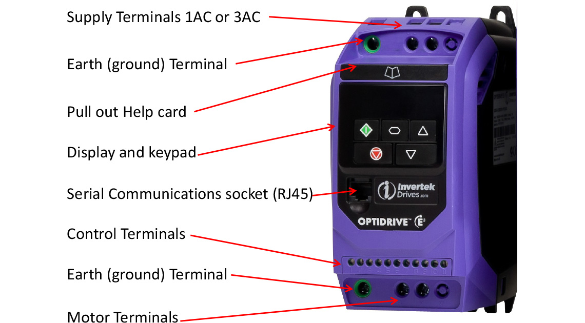
Installing a variable frequency drive is pretty straightforward, but bear in mind it needs to be kept cool. This means there should be good airflow around the VFD, and the manufacturer’s recommendations (read the instruction manual!) concerning spacing around the unit should be followed (read the instruction manual!). Don’t block airflow with cable trunking! Make sure the air supply is clean and free from dust, dirt, fluids etc. Figure 1 shows the location of the key parts on an IP20 E3 drive. IP66 units have enclosed terminals of course, and larger power drives have the terminals at the bottom.
If the drive is enclosed, consider the worst case temperature rise. The variable frequency drive dissipates heat, and this may add to other losses from equipment in the same enclosure, warming everything up. A ten or twenty degree rise in a cabinet may be OK in the UK, but may be excessive in an Indian summer. Application Note AN-ODE-2-070, available on the Invertek website (invertekdrives.com) gives lots of information about calculating temperature rise and other installation matters.
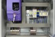
Once the variable frequency drive is installed, we should think a little about EMC and plan the wiring accordingly. All electrical equipment generates electromagnetic interference (EMI) and most equipment is designed to ensure it is compatible with other equipment; that’s what EMC (electromagnetic compatibility) is all about. Installation and wiring can make the difference between reliable operation and expensive site visits, although in general this is not as great a problem as in the past.
However, make sure you follow basic guidelines when it comes to wiring up. There is plenty of information in the application note, but with modern variable frequency drives it is all about using screened or armoured cable for the motor connection (grounded at both ends), and ensuring good grounding all round.
Figure 2, from the application note, shows the basic principles of good EMC practice. Notice that the control cables are separated from, and at right angles to, the power cables, which are screened or armoured.
.jpg)
With the mains power and the motor connected, just check again that:
- The supply matches the drive. As mentioned earlier, some variable frequency drives are designed for a 230V supply and will certainly fail when connected to 400V.
- The motor voltage also matches the supply, and in the case of a dual voltage motor it is connected in Star for low voltage and Delta for high voltage operation.
- You haven’t connected the supply to the motor terminals and vice versa. This happens!
- The VFD and the motor are correctly grounded.
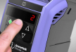
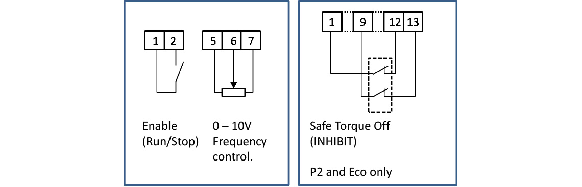
Now you can connect (or check) the control wiring. If the drive has built in controls this may not be necessary. On drives without controls, this will usually consist of at least a switch or link between terminals 1 and 2 to enable (start) the drive. This is required in nearly all control modes, even if the variable frequency drive is to be started from a serial link or front panel.
On drives such as the P2 and Eco (but not E3) drives additional connections (for example, links) are required from the Safe Torque Off terminals to 0V and 24V terminals. If you haven’t done this the display will show INHIBIT.
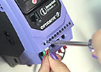
The output frequency (and therefore the motor speed) is often controlled by a 0 – 10V signal applied to the analog input. A potentiometer may be connected directly to the control terminals, or a 0 – 10V signal supplied from an external source such as a PLC. Figure 3, taken from the manuals, shows the basic connections to get started.
In any case, take a look at the manual or the help card (which is built into the drive) for basic wiring information.
Now you’re ready to commission the variable frequency drive; we’ll look at this in the next article