Using the Inputs on a Variable Frequency Drive
Article 7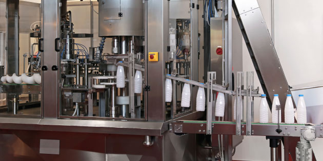
In the last article we looked at the basic parameters and how they are used to set the drive up to match the motor and the application. Now we’ll look at some of the extended parameters, which allow more advanced settings.
Most variable frequency drives have several analogue or digital inputs that can be programmed for different functions using parameter settings. The Invertek E3 has two dedicated digital inputs, and two analogue inputs, which can also be used as digital inputs. Very flexible.
There are many different ways of controlling a variable frequency drive (serial interfaces, keypad, closed loop etc.) but the control terminals with their digital and analogue inputs are still the most popular.
Each input can have many different functions. Digital inputs can be programmed as Run Forward, Reverse, External trip, select preset frequency, switch between analog or preset frequency references etc. Analogue inputs are usually used for a frequency reference input, but may also be used to monitor a feedback signal (such as pressure or flow rate) from a transducer to facilitate closed loop control. As many combinations of these settings are possible, Invertek variable frequency drives offer a selection of ‘favourites’ to make life easier. P2 and Eco drives are more flexible and are a little different – see later.
If you have an IP66 drive with built in controls, remember that changing the parameter settings will change the function of these controls.
To select these favourites we’ll use parameter P-15; to access parameter P-15 we’ll need to change the access code in parameter P-14. The default access code setting is 101 (201 to access some advanced parameters). You can change this code if you want (P-37), but it isn’t recommended.
Now P-15 allows a wide range of settings to be selected; however these are dependent on the setting of P-12. The last article explained that P-12 selected the main source of control for the drive, so it makes sense to change the digital and analogue inputs to match these different requirements. All will become clear; let’s start by looking at the settings of P-15 when P-12 is set to 0, the default setting of terminal control.
At the last count there are seventeen different settings of P-15; this figure changes as the applications for E3 grow and the firmware is adapted to suit customers’ needs. The handbook shows fifteen settings and will be updated in time. The latest firmware variation can always be seen using Optitools Studio – but more of that later.
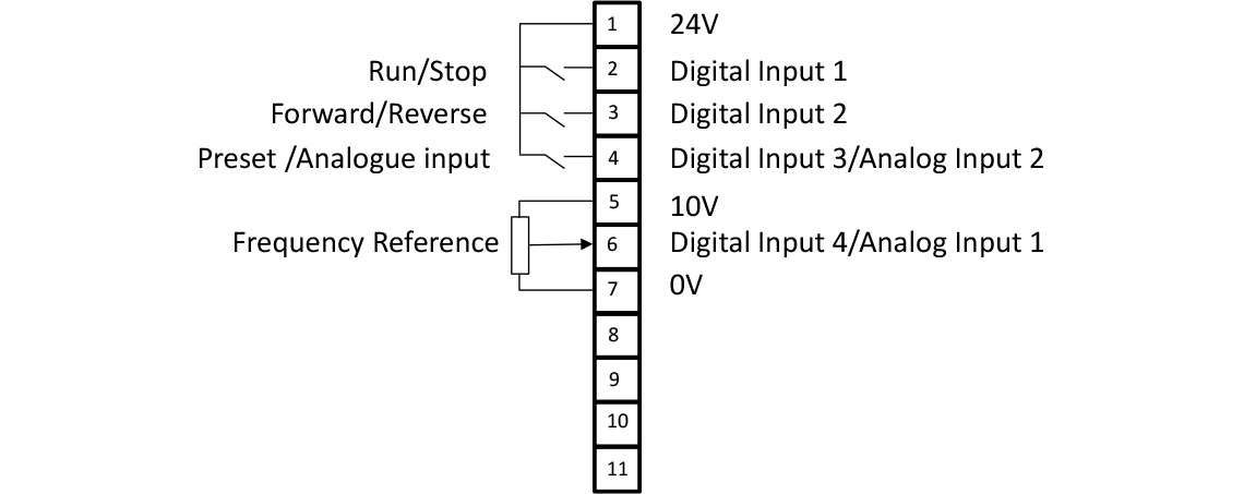
With P-15 = 0 (and P-12=0), the default setting of digital input 1 (DI 1 for short) will be the stop/start input, DI 2 the reverse.
DI3 and DI 4 can also be Analogue inputs, so we’ll label them DI 3/AI2 and DI4/AI1 to be correct.
DI 3/AI 2 works as a digital input here and will allow switching between a preset frequency and the analogue input as a frequency reference.
Incidentally, a ‘high’ or active signal here is defined as between 8 and 30V; a low as 0 to 4V – pretty much industry standard.
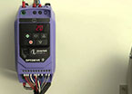
DI 4/AI 1 (as an analogue input here) is the input for the frequency setpoint; a 0 to 10V signal here will control the output of the drive between 0 and 50/60Hz (with the default settings). The connections and terminals are shown in Figure 1
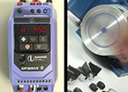
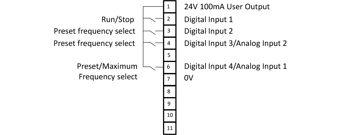
So that’s the default setting; good enough for many applications. However, suppose we want to use preset frequencies instead of an analogue input. Maybe a machine runs at ‘Slow’, ‘Medium’, ‘Fast’ and ‘Clean’ settings. With P-15 set to 2, DI 1 still starts and stops the variable frequency drive, but DI 2 and DI 3 now select some preset frequencies that you’ve set in parameters P-20 to P-23. DI 4/AI 1 (Now a digital input) switches between the maximum frequency and whatever DI 2 and DI 3 have selected. We select up to four preset frequencies using two digital inputs with binary coding, which is a bit confusing, but the handbook helps here. This is shown in Figure 2.
The rest of the settings of P-15 allow other functions to be used. For example, if you want to use a digital input as an external trip (this would be normally ‘high’ to run) settings P-15 = 3, 6 and 7 include an external trip function on DI 3. Other favourite combinations allow the use of fast stops, run forward/run reverse combinations etc.
Push button control, where the signal is momentary, is catered for with P-15 = 11. There is even a ‘Fire’ mode for Building Management applications, where the drive runs regardless of trips, warnings and other commands. Check out the handbook to see the selection.
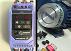
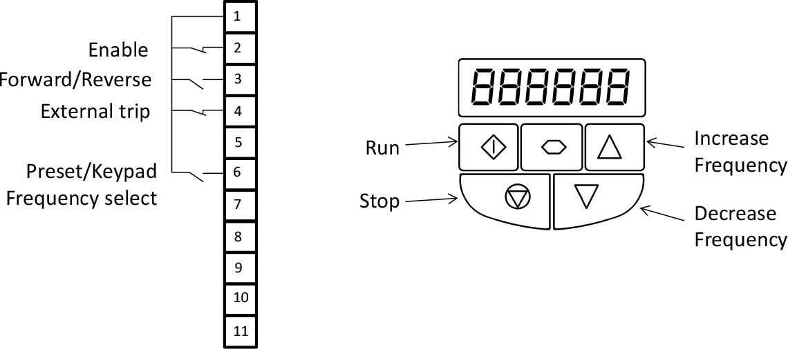
If we now change P-12 from its default setting, the functions of P-15 change to suit. So when P12 = 1 or 2, you can control the drive from the front panel keypad; you’ll still need a ‘high’ on DI 1 though. P15 settings now allow some additional functions over the terminals. P15 = 6 for example allocates Run forward/reverse, external trip and Keypad/preset select to DI 1 to 4 respectively. This is shown in figure 3.
With P12 = 3,4,7,8 or 9, the drive is controlled from a serial link control such as Canbus or Modbus. Now setting P15 = 6 for example, sets the inputs to [DI 1] Enable (as usual), [DI 2] switch between Fieldbus/Analogue input frequency reference, [DI 3] External trip and [DI 4/Analogue input] Analogue reference input respectively. We’ll discuss serial control in a later article.
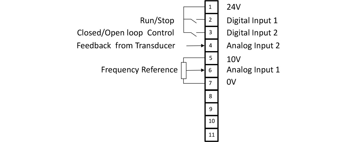
With P12 = 5 or 6 we’re working in closed loop control. We’ll discuss this mode in another article, but suffice to say that the P-15 settings allow the use of analogue inputs for frequency references and feedback inputs, as well as switching between open and closed loop control. Fire mode inputs can be enabled in closed loop control if required. Figure 4 shows a typical closed loop connection.
So, settings of P-15 and P-12 offer maximum flexibility while keeping things reasonably simple. However, P2 and Eco drives are little more complex than E3, so there are a few differences. For historical reasons, P2 and Eco drives have different parameter numbers – as well as parameter groups compared with E3. So P1-13, not P-15 is the parameter to adjust the input settings, and there are many more settings available. P1-12 still affects the settings of P1-13 in the same way.
To give maximum flexibility, P2 and Eco also allow each function to be allocated to a digital input, So if you want to have two reverse inputs and an external trip, as well as a run stop control, this should be possible. This gets a bit complicated, but it’s worth knowing you can do it if you want.
In the next article we’ll look at the different ways that drives can save energy.