Serial Communications
Article 11
We’re all familiar with serial communications; the USB connections on our computer use serial communications to connect to the mouse, keyboard and memory stick. Although wireless and Bluetooth are partially replacing the actual cables, the principle is still the same.
However, when it comes to drives, many users still prefer simple, hard wired control connections. These are fine in small installations, and are easy to de-bug, but in more complex installations serial comms can make a lot of sense, replacing lots of cables and enabling easy set up from a laptop. Nearly all drives have serial comms built into them as standard, so often there is little additional expense in moving over to serial comms.
So what are they and how do they work? Well, at its simplest, serial comms involves sending a string of digital pulses – 1’s and 0’s to (say) a variable frequency drive which will interpret them, act on them and maybe send a signal back. To make this work, we need to define the hardware, for example how many volts a 1 or 0 is. We then need to decide on a protocol to work out who sends what and when, otherwise the signals will get all mixed up. We also need to decide how we structure our signal so it goes to the right place, with some form of checking. Finally, we need to define what the 1’s and 0’s mean.
Defining the hardware is pretty straightforward. We can use wireless or fibre optic cables, but for low level industrial applications we often use simple cables and signals defined by RS485, a well established standard designed for noisy applications in industry. Figure 1 shows how signals in the two cables switch in the opposite sense to one another with respect to 0V.
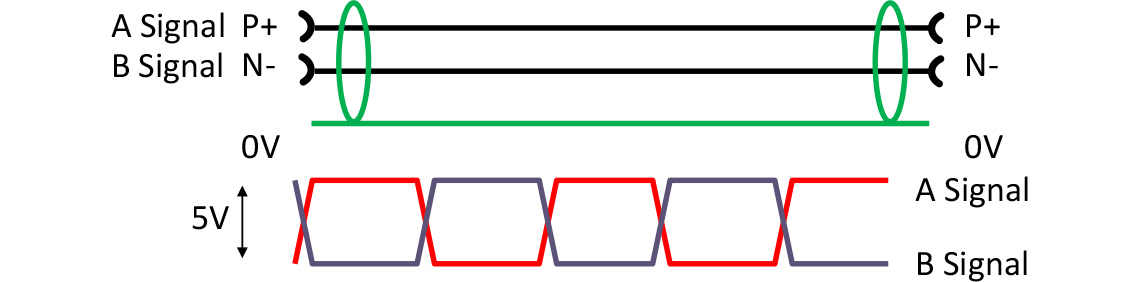
This gives high noise immunity, but you must ensure the ground in the whole system is common, perhaps by using two wires inside a grounded screen – connected at both ends - to connect between different points or addressable locations (nodes).
Now we need to decide the signal protocol. One way is to define a master and slave (or slaves) system. The master always starts a ‘conversation’; the slave replies only when spoken to. This system is easy to understand, and also allows broadcast messages to all slaves, providing they don’t reply to a ‘broadcast’ message. Many industrial communications use this system. A variant of the master slave is the token system; whoever has the token is the master, but it can be passed around. These systems avoid collisions which lead to corruption of signals.
However, with Ethernet types of transmission (the system used on the internet), collisions are allowed. Basically anything on the system can try to send a signal; if there is a collision, you stop sending, and try again. The existing signal on the network is sent again if it has been corrupted. Ethernet has been optimised for very fast operation, and uses many different media such as fibre, wireless, and of course the familiar Ethernet cable. The Internet has expanded to the World Wide Web basically using this principle. Ethernet systems are increasingly popular in industry because its widespread use in computing has developed the technology and reduced the price. However, each node requires a router to detect and control collisions.
Although fast, Ethernet is not time determinant. That is, you may need a short or long time to grab the bus and send your signal, whereas with a master slave system the master has perfect control in terms of timing; important when you are controlling complex machines. Ethernet systems have developed work arounds for this.
The system Canbus (a system developed for in-car use and now popular in industry as well) allows prioritisation of signals; you grab the bus, but a higher priority signal will take it over from you. Important when you control braking systems.
So one way or another we have a protocol that allows signals to get around without being corrupted – or if they are, as in the case of Ethernet, then it’s sorted out. We now need to define exactly what our signals mean. Of course, we can make our own serial comms system if we want, but if we adopt an existing one, it will be easy to find hardware and software to help us. A while ago, several companies using their own serial comms decided it would be in their interest to define how the signals were structured, and to release these definitions to all, thus encouraging their use. These systems are known as open, or Fieldbus systems, and are often defined by a formal document such as a Euro norm. Examples are Profibus, Canbus, Devicenet, Bacnet and Modbus; most of these Fieldbus systems now also have an Ethernet variant.
Most fieldbus systems start by defining the hardware, usually RS485, but increasingly Ethernet cable and systems, or fibre. They then define the protocol – often master slave, but with Ethernet, collision systems with defined areas for time determination. Finally, they define a telegram structure- a block of data that carries the information.
Let’s look at a couple of examples. Modbus is a common Fieldbus system, which uses (among others) RS485 hardware and a master slave system. Figure 2 shows the basic telegram structure.
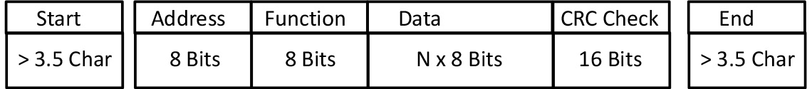
There’s a space at the beginning and end of the telegram and then the first eight bits of the signal define the destination address – only eight bits so only a limited number of nodes on a system is possible. Then there’s a function code; in its simplest form this is a code such as ‘03’ meaning read or ‘06’ meaning write. Then there’s the data; this could be a parameter value, a setpoint, or whatever. Finally, there’s a checksum to make sure the whole telegram hasn’t been corrupted.
The way Modbus works is that the Master will write to the slave asking to read or write some data, and the slave will give the information back or write the data as instructed. These read or write actions are carried out using a block of registers in the Master or Slave. The Master or Slave interprets the data in these registers as parameter values, measurements (such as output frequency, load current) etc.
An Ethernet telegram is a more complex structure, shown in Figure 3, but with the same basic information.
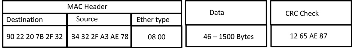
Now we have a source and destination MAC address (unique to each machine in the world!) a couple of words that define the type of signal, and then the data packet, the payload. Finally a check sum to make sure the signals OK. With the speed of Ethernet we can transmit vast amounts of data, but a disadvantage of Ethernet net is that a router is needed at each node. Industrial Ethernet systems define short ‘channels’ in time between standard signal areas which can be used for critical time dependent control. This allows Fieldbus derivatives such as Modbus TCP and Profinet to use Ethernet in and industrial environment to great advantage.
Fieldbus based serial comms systems are pretty widespread throughout industry. Well established systems such as Modbus, Canbus and Profibus continue to grow at about 7% pa, but Industrial Ethernet is growing faster, typically 20%.
Invertek variable frequency drives support some common fieldbus systems as standard, and may be fitted with simple adaptors to work with many others.