What is a Variable Frequency Drive?
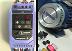
Article 1A variable frequency drive (VFD) is an electronic device that controls the speed of AC induction motors. Before we look at how this works and how it can be used, we should look at the history of motor controllers, and also how the induction motor itself works.
It has always been useful to control the speed of electric motors used in industry. Nearly every process that uses a motor will benefit from speed control. Not only is the process generally improved, but in many cases (particularly with pumps and fans) these is considerable energy saving.
Before electronic controllers were available, motors were controlled in various ways, for example by controlling the field current on a DC motor using a series of resistors, or by using other motors. However, when Thyristors, the first power semiconductors, became available in the 1950’s, it became possible to control the armature voltage, and therefore the speed, of a DC motor using phase control. These DC drives are still manufactured and in wide use today.
However, the challenge has always been to control the speed of the AC induction motor, also known as the Asynchronous motor. While a DC machine usually has two wound parts (the field and armature windings) as well as brushes and a commutator, the AC machine has a simple, fixed winding (the stator) and a rotor. The rotor usually consists of conductors formed by casting Aluminium or Copper in the iron core. There are no brushes or commutators. The machine is therefore cheaper, simpler and more reliable. It is little surprise that these machines make up the majority of motors used in the world’s industries. So how does it work, and why does it need a variable frequency drive?
Let’s start by looking at a three phase transformer, shown in Figure 1
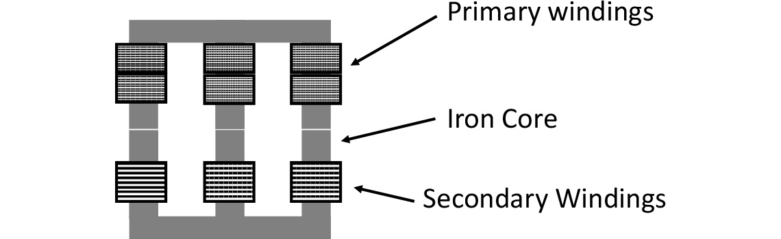
If the transformer winding is connected to a three phase AC supply, a sinusoidal current will flow in the primary windings. The current will cause a magnetic flux to be induced in the iron core of the transformer, which will rise and fall as the applied voltage (and therefore current) alternates, usually at 50 or 60 Hz, depending on the power system.
The changing magnetic flux will then induce a voltage in the secondary windings, and if a load is connected (or even if the windings are shorted together) a current will flow. The ratio of the turns of the primary and secondary windings will determine the ratio of the primary voltage and the secondary voltage, which is why transformers are so useful.
Now imagine that we roll up the windings, make a small air gap between them, and allow the secondary winding, now called the rotor, to move freely. This is the basis of the induction motor, shown in Figure 2.
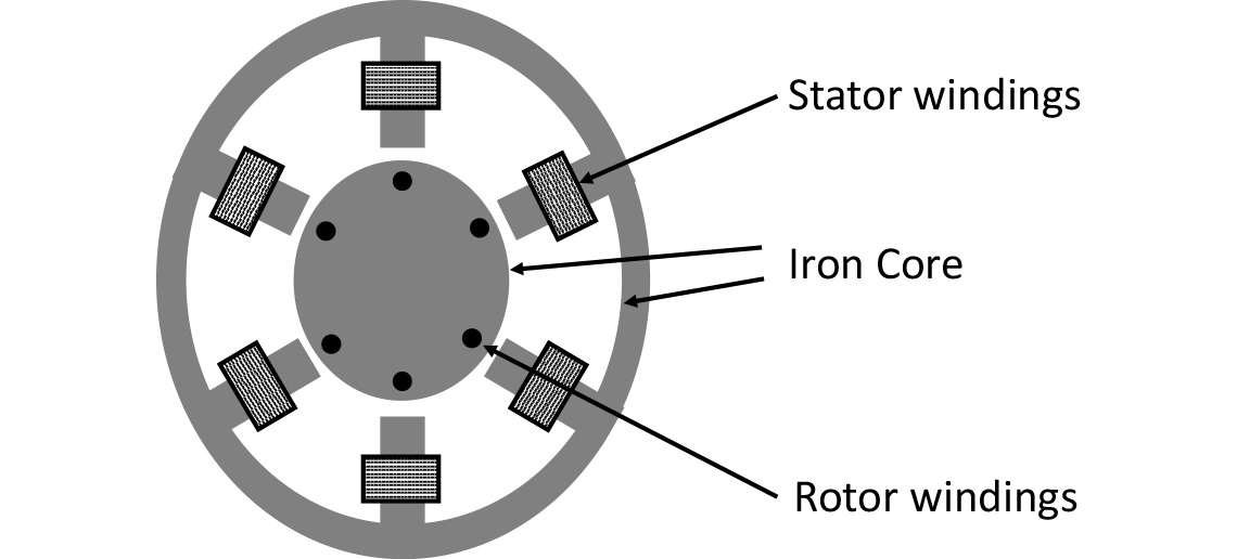
So when we connect a three phase supply to the primary winding – now called the stator, we have transformer action as before, and current flows in the rotor (secondary) windings. As mentioned above, the rotor usually consists of cast conductors within an iron core with a shorting ring at each end. As this arrangement appears a little like a circular cage (ignoring the Iron of course!) the motor is sometimes referred to as a squirrel cage motor. In the Figure 2 the conductors are perpendicular to the diagram, and the shorting rings not shown.
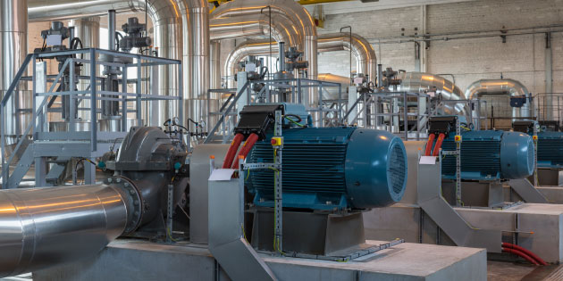
Figure 3 shows a typical motor construction.
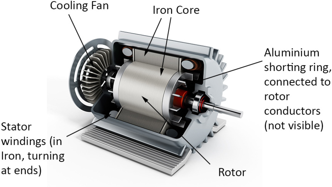
Now if we have a magnetic field and an electric current, we get a force, and according to Fleming’s Left Hand Rule this will turn the rotor, so we have a motor. However, as the motor speeds up, it begins to ‘catch up’ with the magnetic field, which is effectively rotating - alternating - around the stator at the frequency of the three phase supply. Now we will only get transformer action as long as the magnetic field is continually changing; transformers only work with AC. So if the rotor catches up with the supply, there is no longer a changing magnetic field, so there is no transformer action, no rotor current, and no torque. So a standard induction motor will always run slightly slower than the applied frequency. This reduction in speed is known as the slip. As an induction motor is loaded, the slip increases a little, more current is drawn, and the motor takes up the load. So the speed of the motor is basically dependent on the applied frequency. In a simple induction motor, this speed will typically be a few percent lower than the synchronous speed (at which no torque is available).
Doubling (or trebling etc.) the number of windings or pole pairs allows this speed to be reduced. So a motor with one pole pair (a two pole motor) running on a 50 (60) Hz supply will operate at say 48 (58) revolutions per second, or 2880 (3480) rpm. A four pole machine, the most common, therefore runs at 1440 (1740) rpm. Six and eight pole motors are readily available, with specialist applications requiring more poles using special motors.
Figure 4 shows the classical torque/speed relationship of an AC induction motor.
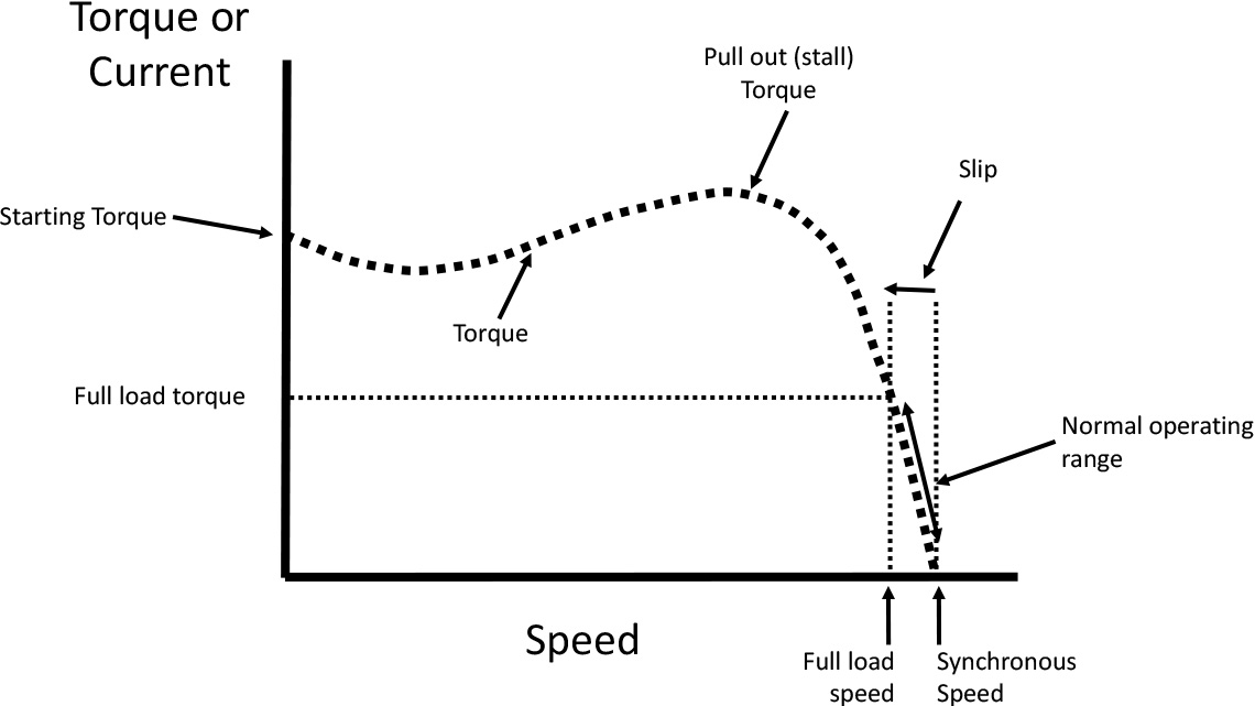
So if we want to control the speed of the motor we need to vary the applied frequency. However, if we manage to vary the frequency, we need to look after the voltage as well, because the magnetising current in the stator depends on the integral of the voltage over time. That is, the area under the curve of the sine wave. If we decrease the frequency then the period, or length of the sine wave increases, so the area under it also increases, leading to excessive magnetising current in the motor. So if we reduce the frequency we must also reduce the voltage applied to the motor in proportion.
We’ll discuss how we do that electronically with a variable frequency drive in the next article.

In the last article we saw that an AC induction motor runs at a speed dependent on the applied frequency with slight reduction in speed, known as the slip. To control the motor speed, we will need to vary that frequency, and also control the applied voltage to maintain the optimum flux, or magnetic field.
Nearly all Variable Frequency Drives work on the basis of taking the existing AC supply, converting it to DC using a rectifier, and then converting it back to a variable frequency supply using an inverter. The inverter is the key part of this, so a variable frequency drive is sometimes simply called an inverter.
Inverters, and to a lesser extent rectifiers, rely on modern power semiconductors that can switch and conduct high voltages (such as supply voltages) and currents of hundreds of Amps. They also require powerful microprocessors to control them. These components have only been available at reasonable cost and reliability in the past thirty years or so, therefore AC drives are a relatively modern industrial product.
So how do they actually work?
Let’s start with the rectifier. Figure 5 shows a three phase rectifier consisting of six diodes connected to a capacitor and a resistor as a simple load.
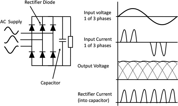
The diodes conduct in one direction only (in the direction that they point); the capacitor stores energy a little like a battery, the resistor acts as a load. If we connect a three phase supply to the inputs on the left we’ll start pumping current into the capacitor, and the voltage will build up, leading to a current flow in the resistor. You can trace the conduction path round from any one phase to another through an upper diode, the capacitor/resistor and then through a lower diode.
In steady state, the voltage on the capacitor will sit pretty near to the peak of the input sine wave voltage. Now the diodes are conducting only when the input voltage is higher than the voltage on the capacitor. Consequently, there is a short pulse of current through each diode in turn, leading to the characteristic ‘twin peaks’ waveform of current in each of the three phases as shown in the figure. If we use a single phase supply we only need four diodes, and we’ll get a single peak per half cycle, so we’ll need a bigger capacitor to hold up the gaps in the voltage peaks.
On single or three phase systems, these pulses of current can have consequences for the supply, as we’ll see later. However, we now have a relatively smooth DC voltage on the capacitor. If we take away the resistor, and connect an inverter instead, it begins to look like a variable frequency drive (figure 6) The DC part is sometimes called the DC link as it joins the rectifier and inverter.
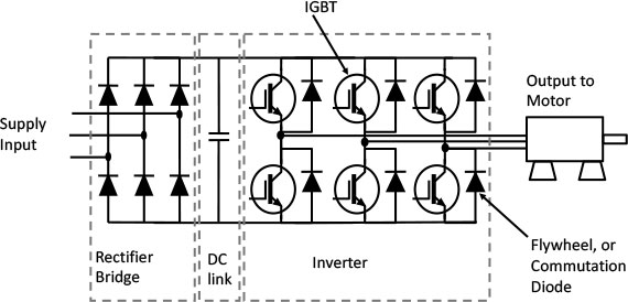
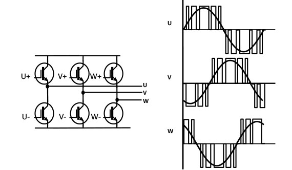
Now to the business part. We have six Insulated Gate Bipolar Transistors (IGBTs). These function as very fast power switches. They have diodes in parallel with them for reasons that will become clear.
We can now switch on an upper and lower IGBT and provide a current path through any two motor connections. To turn an IGBT on, we simply apply a few volts to the gate (shown here unconnected). Then the IGBT conducts in the direction of the arrow. Depending on which IGBTs we turn on, we can create a positive or negative current path though the motor. Hence we can make AC from DC.
What we don’t do is turn on an upper and lower IGBT which are directly on top of one another as this would provide a short circuit to the DC link. If instead we turn on and off IGBTs in a carefully controlled sequence, we can build up a three phase current in the motor windings. If we vary the time that we switch the IGBTs on and off for, we can control this current. This is because the motor current doesn’t change very rapidly, so by increasing and decreasing ‘on’ times, we can choose to build up a sine wave current in the motor at practically any frequency we wish. This, of course is what we want to do to control the motor speed. Using the same technique, we can control the effective voltage, which in turn controls the magnetic field.
This on off time control is called Pulse Width Modulation (PWM), and is shown simplistically in Figure 7; switching the six IGBTs on and off provides current paths to the motor and allows a three phase sine wave current to flow, turning the motor at the desired speed.
If we switch our IGBTs several thousand times a second (usually between 4 and 16kHz) we can build up quite a nice current waveform as shown in figure 8.
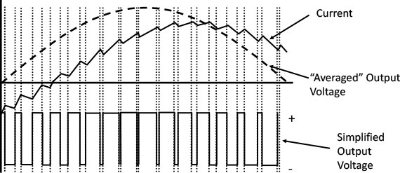
Notice that the output voltage consists of lots of pulses rather than a nice sine wave. The motor smoothes the current to a slightly jagged sine wave, but the voltage still consists of the PWM waveform from the IGBTs. This can cause problems that we’ll discuss later. However, the motor is happy with the jagged current and turns at the required speed. The motor current is out of phase with the ‘average’ voltage due to the motor power factor.
So what are the diodes doing in the inverter? Well, the current in the motor doesn’t change very quickly, so when we switch off an IGBT the current needs to keep flowing, or there will be problems. The diodes automatically provide this current path by switching on, or commutating, the current. Hence the name commutation or flywheel diodes.
Inverters are very difficult to control – they’ve been described as a short circuit waiting to happen, but modern power semiconductors are pretty robust, and fast, powerful digital signal processors allow reliable and precise control of the on and off switching.
By the way, the power part of the variable frequency drive is all connected to the AC supply, and operates at DC voltages from 300V (with a 230V AC input) up to 600 - 900V with industrial three phase supplies. So internal isolation between the control circuits, customer interfaces and the power part is safety critical.
In the next article we’ll look at the practical design of a variable frequency drive, with all the complexity of protection, cooling and interfacing to the customer.