Problems with motors and cables
Article 22
Motors are designed to work with a fixed frequency and voltage from the mains, which is a nice smooth sine wave. In the early days of variable frequency drives, motors were hit with some pretty nasty waveforms that were more like square waves than sine waves. Turned out that they were surprisingly tolerant of these distortions, and although there was a lot of discussion about harmonic heating, we generally got away with it. With improved power devices like IGBTs, switching frequencies gradually increased and the current waveform improved accordingly. However, while the current waveform is approaching a sine wave, drives still generate a voltage waveform that is basically a stream of high voltage square wave pulses (see article 2).
A square wave is made up of a mixture of many frequencies, including some much higher than the fundamental switching frequency. Higher frequencies are ‘leakier’ than lower ones – that is, they tend to radiate, and find paths through stray capacitance, causing problems. A good example of this is what happens when cables are connected between the drive and the motor.
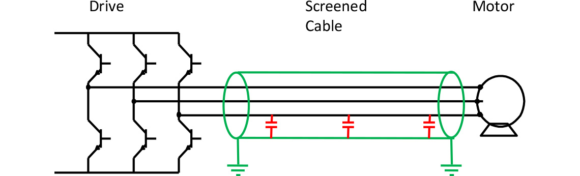
There will always be a stray capacitance in cables from conductor to conductor and from conductors to earth. The closer the conductors are to an earth, the greater the capacitance. Screened cable is always recommended to connect between the drive and motor, because this ‘contains’ the interference created by the switching waveform. However, as the screen is connected to earth, it means there is significant capacitance between the conductors and the earthed screen. The longer the cable, the greater the capacitance, as shown in Figure 1.
When drives were first tested and developed, the engineers usually worked with a short cable from the test bench to the motor underneath, so it wasn’t until the drives got into the real world that long cables were connected and the problems started.
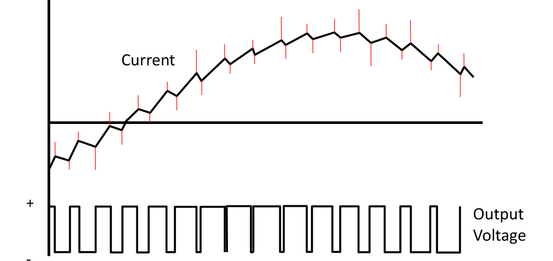
As the IGBTs in the output of the drive switch on and off they have to charge and discharge this stray capacitance. Or to put it another way, the high frequency content of the waveform supplies current to the capacitance. The result is that spikes appear on the (relatively) smooth output current of the variable frequency drive. Figure 1 shows the current spikes caused by cable capacitance (in red) superimposed on the ‘normal’ current waveform.
These spikes occur just at the time the IGBTs are switching, so they increase the switching losses in the inverter, and the drive runs hotter. If the cable is too long and the capacitance becomes excessive, the drive may overheat and will trip on over temperature. Sometimes the spikes are large enough to cause the occasional over current trip. All very annoying.
Once the drive designers woke up to the problem, they started testing the drives with long, screened cables, and established exactly how long a cable a particular drive could work with. Nowadays most drives are tested, and are specified to work with, screened cables of typically 50m - sometimes more, sometimes less, depending on the drive. If you need to work with longer cables, you can fit various filters, or sometimes just an output choke.
But possible snags don’t stop with the cable. Once the inverter output reaches the motor, the high frequency content can cause more problems. Originally, motor insulation was designed for operation with a nice, simple, smooth mains voltage with only occasional disturbances. Along came the variable frequency drive and the insulation on old motors just wasn’t up to the inverter output. Stories of new fangled drives breaking old reliable motors spread, and motor manufacturers worked hard to improve their designs. New insulation materials, and changes to the way the windings fitted around the stator end in the motor fixed the problem. Motors less than thirty years old are generally ‘inverter ready’. Consequently insulation failure nowadays as a result of using a drive is pretty rare. If the insulation has failed on a motor it is usually as a result of overheating or just ageing. If the motor is old, it should be replaced anyway – a modern, efficient motor will pay for itself in a few years.
A rarely seen effect is voltage doubling. If the cable is a length that (unfortunately) coincides with a multiple of the wavelength of one of the high frequency components of the switching waveform, the voltage at the motor terminals can be doubled by reflected signals. Again, most motors are rated for this, but damage may occasionally occur. The solution is to add a bit more (or less) cable to the connection.
Another problem caused by the high frequency content of the drive is bearing currents. Again, stray capacitance from the motor windings to ground is the culprit. The high frequency current finds all sorts of routes to ground, including flowing through the motor bearings. This results in a slow erosion or etching of the bearing surface, producing curious patterns on the bearing race which, curious or not, lead to bearing failure. The problem usually occurs in higher voltage drives and larger motors, but occasionally will be found in smaller installations.
Again, motor manufacturers have responded by using insulated bearings (usually only one is necessary, often at the non drive end) in many – but not all – motors.
Prevention of bearing damage is better than cure of course, and there are a few simple precautions that drive users can take to minimise the problem.
Good grounding of the motor will ensure that leakage currents flow through the body of the motor, rather than the shaft and bearings. Grounding of the motor and the system can be improved using braided ground straps that have good high frequency conduction. In general, good EMC practice (proper termination and grounding of cable screens for example) will minimise leakage currents. Symmetrical cable seems to help; that is screened cable (between the motor and the drive) where each conductor has the same leakage to the screen. Cables that have additional grounding cables that are symmetrically distributed within the cable are also beneficial.
Shaft grounding brushes are available, and will bypass the bearings and prevent damage, although these should only be considered where bearing damage has proved problematic in the past.
Fitting an output filter is probably only a last resort, as these are expensive and bulky, but by removing the high frequency component of the switching waveform they will greatly reduce leakage current – and allow longer cables to be used.
These problems are all relatively unusual and most drive installations are commissioned and operate without problems. However, when they do turn up, they can be tricky to track down.