Safety and Safety Inputs
Article 18
Industrial safety is of key concern to all who work in industry or who design equipment for industrial or commercial application. It’s no good moaning about ‘Health and Safety gone mad” – Safety rules and regulations have saved hundreds of lives. No one would want to emulate certain developing countries where the death toll at work runs to thousands each year. In any case ignoring or ignorance of the rules can end you up in jail.
In the past, safety was a case of visible, electromechanical interlocks, isolators with locks (or in the case of large plants, many padlocks) contactors and switches and obvious disconnection of cables etc. If in doubt, put the fuses in your pocket and your padlock on the isolator.
These days, life is more complicated. Equipment may be started and stopped by control systems a long way from the machine itself, and plant runs up automatically. Consequently, stricter controls and rules are imposed, and additional safety systems installed. Emergency stop buttons appear all over the place.
Safety rules and regulations are often seen as a complex and specialist area. Of course, it is important that a competent person has taken responsibility that equipment is safe, but the actual standards are reasonably easy to understand and implement. They also provide guidance and advice on how to assess and reduce risk. Recent standards relate better to modern equipment and have replaced a collection of older, outdated standards, such as EN 954-1.
IEC 61508 (Functional Safety of Electrical/Electronic/Programmable Electronic Safety-related Systems) is an example of a newer standard. This is a general purpose standard that is applicable over a wide range of industrial processes and machinery. It gives clear guidance on how to assess risks and hazards in terms of how often a fault might occur, and what the consequences would be (injury, death, many deaths etc.)
From this assessment the Safety Integrity Level (SIL) can be derived. SIL 1 is the least dangerous, SIL 4 the most. Once the SIL level is determined, the protection equipment with the same or greater SIL level can be selected to provide the protection.
Additional standards may be applied to complete equipment, for example, EN 62061 which relates to machines, and EN 13849-1, which deals with control systems. EN 13849-1 also introduces the concept of Performance Levels, PL a to e, which are similar to, but not the same as SIL categories.
A practical problem is that switching off complex machines to change a tool or free a blockage means a time consuming restart and reboot, which leads to delays and may need the help of an engineer. This particular difficulty has now been overcome on many machines by the inclusion of certified safety inputs. The idea is that dedicated inputs to a piece of equipment (in this case of course, a variable frequency drive) will ensure the equipment is set to a particular state, such as disabled. What makes these safety inputs different to standard run/stop inputs is that they are tested and certified by a third party regulator, so that they are guaranteed to (for example) prevent the drive from starting. The guarantee will allow the user to ‘lock out’ the drive in cases where serious injury or death (depending on the risk level) may result from the variable frequency drive running inadvertently.
Safety inputs can guarantee various conditions such as Safe Torque Off (STO), Safe Limited Speed (SLS), Safe Speed Range (SSR) etc. The most common, and the most useful, is the Safe Torque Off setting, which disables the drive as described earlier.
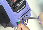
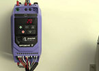
Invertek P2 and Eco drives have implemented this by having two inputs that must be connected to the drive’s 0V and 24V supply, available on the control terminals, as shown in Figure 1.
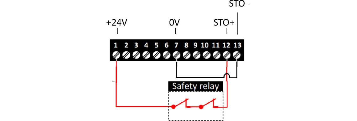
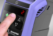
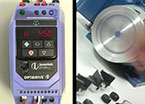
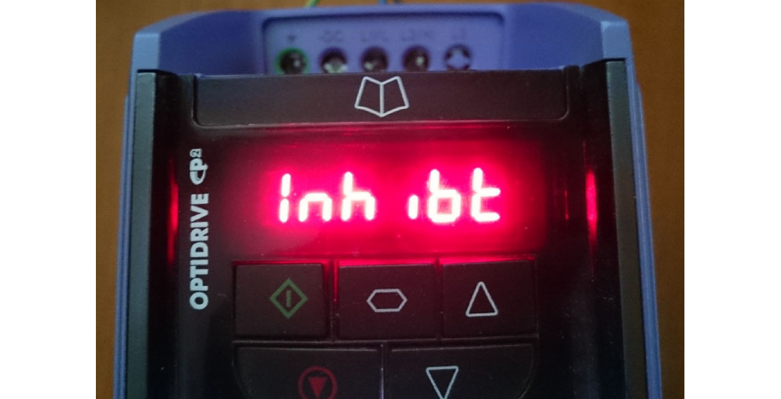
If either of these connections is open, the drive is inhibited. In Figure 1, a safety relay is connected in the STO+ connection. Figure 2 shows the display in the event of a break in the connection.
Remember you will need to bridge out these connections if you are not using this function.
These inputs are fully tested and certified by an independent test house that specialises in safety systems. These safety inputs are read by the system software and will stop the drive, but, because it is difficult to prove the software is perfect and will never make a mistake, the safety inputs are also the supply connections to the IGBTs (the power devices), so it is self evident that the motor cannot be driven by the drive, even if the software is in error.
In the worst case, even if there is a hardware failure in the drive, there may be dangerous voltage on the motor, but it will not be driven.
Getting this level of certification is not easy. The certifying body must understand how the variable frequency drive works, and how the safety inputs ensure the correct response of the drive. After all, they’ll be sued along with everyone else if things go wrong.
Different applications require different types of protection. In the end there is nothing better than an E Stop button that will remove the power from a machine (or a significant section of the plant) in the event of an emergency.

The Safe Torque Off function is really more about disabling a machine but keeping the power on it in order for it to be safe to work on. Now that this useful feature is available and certified on many drives, risk assessment and machine design is a little easier.
Remember to follow the guidelines in the relevant standards and follow the correct procedures; information in this article does not constitute advice on safe installation of variable speed drives.