Commissioning a Variable Frequency Drive
Article 5
In the last article we selected and installed our variable frequency drive. Now we’ll look to commission it – that is, run it up and check it out.
It is always good to start by getting the motor turning if it is safe and easy to do so. As mentioned in the previous article, the Invertek variable frequency drives are preset to run using control from the terminals, so we can get started easily. Summarising the connecting up and checking that we covered in the previous article:
- Check again the supply voltage is correct for the drive, and the supply is wired to the correct terminals.
- Check the motor is also correctly configured for the inverter output voltage.
- Check the variable frequency drive and the motor are correctly grounded.
- To control and run the drive from the terminals:
- Connect a switch between terminals 1 and 2. This is your run stop switch.
- Connect a 5k or 10k Ohm potentiometer to terminals 5 (10V) 6 (analogue input) and 7 (0V). The ‘wiper’ – often the middle terminal of the pot - should go to terminal 6. Alternatively, connect a 0 -10V DC power supply to terminals 7 (0V) and 6 (analogue input) of the variable frequency drive.
- For P2 and Eco drives, link the two Safe Torque Off inputs to 0V and 24V by connecting terminals 1 and 12 together and also terminals 9 and 13 together.
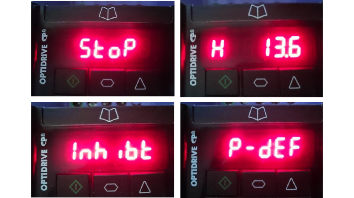
Now you can connect mains power to the drive. Assuming you haven’t changed any settings, the display should light up and display STOP. Close the switch between terminals 1 and 2. Depending on the position of the pot, or the power supply connected to pin 6, the display will show an output frequency of somewhere between 0 and 50. On Eco drives there will be a delay of a second or two before the drive responds to the start command; we’ll explain this later. The H on the left of the display stands for Hertz. If the display is more than a few Hz, the motor should also be turning. Turning the pot or varying the power supply connected to terminal 6 should vary the output frequency and therefore the speed of the motor. Open the switch between terminals 1 and 2 and the output frequency will fall to 0 and then the display will show STOP as before.
Troubleshooting
Didn’t go to plan? Well, the drive is probably OK. Every Invertek variable frequency drive is fully tested before leaving the factory, including short circuit and overload tests, so if you’ve just taken it out the box and connected it up it’s unlikely you’ve broken it. Let’s make some common sense checks.
- Did the display light up when you applied power? If there is anything at all in the display then a lot of the electronics is working. If there is nothing, check and check again you’ve connected the mains supply correctly.
- Does the display show INHIBIT (P2 and Eco drives only)? If so, you haven’t made the safe torque off links correctly. Check the links between terminals 1 and 12 and between 9 and 13.
- Is the display showing STOP? Check you haven’t started the drive already; the connection between terminals 1 and 2 should be open, and when you close it the drive should run (i.e display an output frequency such as H 10 ).
- If the output frequency doesn’t change as you vary the Pot or the dc power supply, check the connections at terminals 5, 6 and 7; measure the voltage at terminal 6; this should vary between 0 and 10V as you vary the pot or power supply.
- Maybe the variable frequency drive has been used before, or ‘adjusted’ by someone. In this case, reset all the parameters by pressing the red, up and down buttons together. The display will show P-def and the parameters will be set back to the factory setting (in the case of P2 and Eco drives, a four button reset – described in the manual, may also be used, but check there aren’t important settings that may be lost before doing this). The drive is now reset to its factory settings; P-def is a trip condition, so to clear the trip press the red button again. The drive should now respond as described above, because the factory settings mean control from the input terminals we’ve connected our switch and pot to.
- If you’ve got a faulty motor, or wired it up wrong, the drive may trip to fault condition as soon as you run it. You’ll see something like O-I in the display, Switch off, disconnect the motor and try again. If the drive runs up OK without the motor then check your wiring or try another motor.
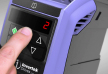
Figure 1 shows some of the displays you might see in a P2 drive; other drives are similar.
Perhaps we should assume now that you’ve actually got a motor turning and that you are happy the variable frequency drive is working and that the wiring is right. If not, we’ll see later that there are some other things we can check before we call up for support.
Now the settings of the drive ‘out of the box’ are a compromise to make it easy to get started, but the real commissioning starts with changing these settings to suit your particular application. The drive settings are adjusted using parameters. Each parameter concerns a particular setting or characteristic of the variable speed drive and may be adjusted (except for read only parameters that give information – more on this later) by the user. Now the drive designer can throw in as many or as few parameters as he thinks he can get away with. Add more parameters, and the variable frequency drive becomes highly flexible – and complicated. Too few, and customers will be asking for the missing features. Invertek variable frequency drives try to keep it simple, and offer just fourteen basic parameters to simplify set up, with the more complex parameters tucked behind a password. Some parameters can be changed while the drive is running, and in any case all the parameter settings will be retained after power down. On the P2 and Eco drives, the parameters are arranged in groups; on the E3 drive, they just number up to 60. As previously mentioned the first fourteen parameters are easily accessible on all drives, and the first twelve of these are virtually the same for all drives. If you need to access the parameters and you’ve lost the manual, there is a help card that lists these parameters built into every drive.
In the next article we’ll look at these parameters, see how to adjust them, and discuss why you might want to.