Braking and Regeneration
Article 14
Most of the time, in most applications, a variable frequency drive controls the motor by supplying it with energy which then powers the load. However, occasionally the energy flow will be in reverse, that is, from the load, through the motor, back to the drive. This will occur if the load is giving up energy, such as when a crane or elevator is lowering a load, or maybe when a conveyer is transporting material downhill. Regeneration, as it is called, will also take place if a high inertia load is decelerated; in this case, the energy stored in the rotating mass flows back through the motor to the drive. Fans often regenerate when slowed quickly.
Of course, if there is significant friction in the system, or if there are other braking effects (such as the airflow through a fan) then the energy returned to the drive may be greatly reduced. However, if regeneration is significant, the energy will get back to the drive. If this happens, the continued operation of the drive will maintain a voltage on the motor, so a magnetic flux will be present, but the phase of the currents will change, so energy – that is current – will flow into the drive from the motor. The IGBTs and commutation diodes work as normal – the diodes don’t act as rectifiers or anything.
As a result, current flows into the DC link and onto the DC link capacitor. Here it charges the capacitor, so the voltage rises. The current can’t go back to the supply (the rectifiers block this), so if regeneration continues, the voltage on the capacitor will continue to rise. To prevent damage, the drive will detect this and turn off the switching of the output IGBTs. Now there is no output voltage and therefore no magnetising current, so the flux in the motor collapses, leaving the rotor and load spinning freely with no more energy returning to the drive. The drive has tripped on overvoltage; this is a symptom of too much regeneration.
We can prevent over voltage trips in several ways. When the system regenerates during deceleration, the easiest solution is to reduce the deceleration; that is, increase the ramp down time. Now the regenerated energy is less over a longer period, and this can maybe be absorbed by the losses in the system or by the drive itself. However, with high inertia loads you’ll probably end up with a very long deceleration time. Another approach is to simply turn off the output of the variable frequency drive and allow the motor and load to coast to a stop. You can do this by changing the Stop Mode parameter P-05 (P1-05 on P2 and Eco) from 0 to 1. Now there is no ramp down, the drive shuts off and the motor coasts.
The disadvantage with this solution is that there is no control of the load and motor during stopping, so you don’t know if and when it will all stop. This isn’t convenient in process industries, but may be ok for a cooling fan.
Neither of these options help if the load regenerates as part of its normal operation, rather than when stopping. If you are continuously accelerating and decelerating, or if your crane or lift is lifting and lowering all the time, a controlled solution is needed. Some applications, such as the downhill conveyer mentioned earlier, or an unwinder, regenerate all the time. The energy which flows to the DC link of the drive must therefore be dissipated.
The solution is to connect a resistor across the DC to burn off the energy, The resistor is switched on and off by an IGBT, built into most industrial drives, which is controlled by the drive software which monitors the DC voltage and switches the IGBT on and off accordingly. This ‘chops’ the voltage, so it is sometimes called a braking chopper. Perhaps a better description is dynamic, or resistive braking. The resistor is not normally included in the drive package, and must be selected and bought separately. This arrangement is shown in Figure 1.
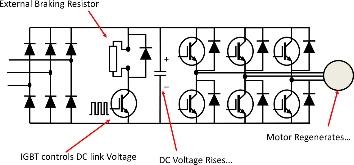
With the correct braking resistor, the drive will now allow typically full load current to be returned to the drive and the power dissipated in the resistor. This allows for controlled lowering of loads and unwinding, as well as rapid deceleration of high inertia loads if required.
As mentioned before, the ‘chopper’ IGBT is usually built into the drive, but the resistor must be selected by the customer. Selection needs a little care. Firstly, any resistor selected must be capable of working at high DC voltage, and must be protected (i.e. fused) accordingly. Secondly, the resistor must have a minimum Ohmic value to limit the current in the IGBT. Then it must be selected to absorb the expected power over the duty cycle of the machine. Finally, consideration should be given to the protection of the resistor. Because of the heat they dissipate, braking resistors are often mounted outside the cubicle, and should be out of harm’s way and protected against liquid, dirt and fingers.
This solution is excellent for low and medium powers, and for control of braking that occurs occasionally. However, if you are operating a container crane that is continuously lifting and lowering large containers, it is wasteful to be burning all that energy in a resistor. The solution here is a fully regenerative drive that will feed energy back into the supply. DC drives were quite good at this, but AC drives need to replace the input rectifier will a fully functioning inverter as shown in Figure 2.
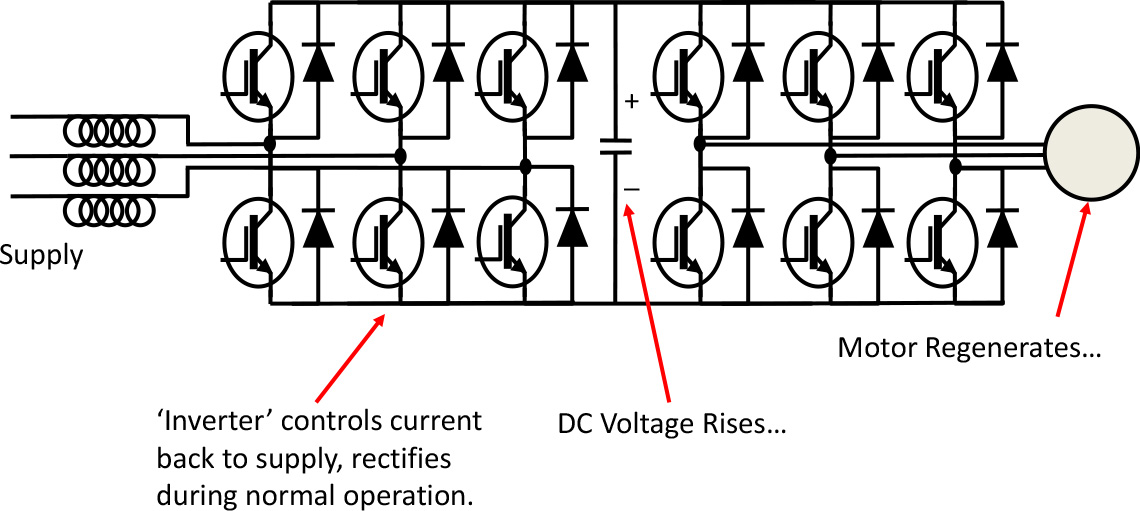
We’ve already established that power can flow both ways through an inverter, so now the regenerative power flows back along the DC link, through the inverter at the front, and back to the mains. An inverter rectifier like this also has the advantage that it can control the input harmonics under normal operation, which can be quite important at these high powers. The extra cost of the second inverter, its control electronics, and the associated inductors required for the system is justified in drives that regenerate above 200kW or so. They are also used extensively in locomotive variable frequency drives as well, so slowing the train pumps power back into the supply rather than wearing out the brakes.
Another trick to recover braking energy in a system with several drives is to connect the DC links of the drives together, so that when one drive regenerates it simply supplies power to another drive that’s motoring. This needs a bit of care; there’s an application note that helps.
E3 Invertek drives include braking IGBTs as standard, except for the smallest unit. P2 drives also have built in braking IGBTs (optional on Frame sizes 6 and above). The Elevator variant of P2 includes a braking IGBT.